REMOVAL AND INSTALLATION
| caution |
|
Pre-removal Operation
- Fuel Line Pressure Reduction [Refer to Multiport fuel injection system (MFI) - On-vehicle Service - FUEL PUMP CONNECTOR DISCONNECTION (HOW TO REDUCE PRESSURIZED FUEL PRESSURE)
 )].
)]. - Engine room undercover front B Removal (Refer to Body - Removal and Installation
 ).
). - Front Bumper Assembly Removal (Refer to Body - Removal and Installation
 ).
). - Engine Oil Draining (Refer to Engine Lubrication - On-vehicle Service - ENGINE OIL CHANGE
 ).
). - Engine Coolant Draining (Refer to Engine Cooling - On-vehicle Service - ENGINE COOLANT REPLACEMENT
 ).
). - Motor Fluid Draining (Refer to EV Cooling system - On-vehicle Service <Oil Cooling system> OIL CHANGE
 ).
). - Motor Coolant Draining (Refer to EV Cooling system - On-vehicle Service <Water Cooling system>EV COOLANT CHANGE
 ).
). - Air Cleaner Bracket Front Removal (Refer to Intake and Exhaust - AIR CLEANER REMOVAL AND INSTALLATION
 ).
). - Power Drive Unit Removal [Motor control unit (MCU)/Motor (Power unit) -Power Drive Unit - POWER DRIVE UNIT REMOVAL AND INSTALLATION
 ].
]. - Radiator asembly Removal (Engine cooling - RADIATOR REMOVAL AND INSTALLATION
 ).
). - Inlet manifold Removal (Intake exhaust - INTAKE MANIFOLD REMOVAL AND INSTALLATION
 ).
). - Transverse link top and Steering gear assembly Remova (Refer to Front suspension member - Removal and Installation
 ).
). - Front drive shaft (Refer to Front axle - Removal and Installation
 ).
). - Catalytic converter (Refer to Engine and motor and emission control - Emission control - Exhaust gas purification device - CATALYTIC CONVERTER REMOVAL AND INSTALLATION
 ).
). - ECM [Refer to Multiport fuel injection system (MFI) - ENGINE CONTROL MODULE (ECM) REMOVAL AND INSTALLATION
 ].
]. - Exhaust front pipe (Intake and Exhaust - EXHAUST PIPE AND MAIN MUFFLER REMOVAL AND INSTALLATION
 ).
).
Post-installation Operation
- Exhaust Front Pipe Installation (Refer to Intake exhaust - EXHAUST PIPE AND MAIN MUFFLER REMOVAL AND INSTALLATION
 ).
). - ECM [Refer to Multiport fuel injection system (MFI) - ENGINE CONTROL MODULE (ECM) REMOVAL AND INSTALLATION
 }.
}. - Catalytic converter Installation (Refer to Engine/Motor Exhaust gas purification device - Exhaust gas purification device - CATALYTIC CONVERTER REMOVAL AND INSTALLATION
 ).
). - Front drive shaft Installation (Refer to Front axle - Removal and Installation
 ).
). - Transverse link and Steering gear assembly join (Refer to Front suspension member - Removal and Installation
 ).
). - Inlet manifold Installation (Refer to Intake/exhaust - INTAKE MANIFOLD REMOVAL AND INSTALLATION
 ).
). - Radiator assembly Installation (Refer to Engine cooling - RADIATOR REMOVAL AND INSTALLATION
 ).
). - Power Drive Unit Installation [Refer to Motor control unit (MCU)/Moto (Power unit) - Power Drive Unit - POWER DRIVE UNIT REMOVAL AND INSTALLATION
 ].
]. - Air cleaner bracket front Installation (Refer to Intake/exhaust - AIR CLEANER REMOVAL AND INSTALLATION
 ).
). - Motor Coolant Refilling (Refer to EV Cooling system - On-vehicle Service <Water Cooling system> - EV COOLANT CHANGE
 ).
). - Motor Fluid Refilling (Refer to EV Cooling system - On-vehicle Service <Oilr Cooling system> - OIL CHANGE
 ).
). - Engine Coolant Refilling (Refer to Engine Cooling - On-vehicle Service - ENGINE COOLANT REPLACEMENT
 ).
). - Engine Oil Refilling (Refer to Engine lubrication - On-vehicle Service - ENGINE OIL CHANGE
 ).
). - Front bumper assembly Installation (Refer to Body - Removal and Installation
 ).
). - Front undercover assembly Installation (Refer to Body - Undercover - Removal and Installation
 ).
). - Fuel Leak Check.
|
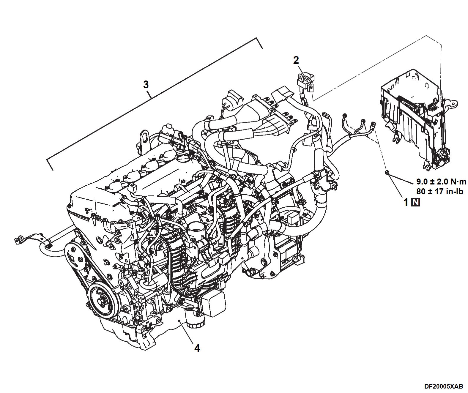
| note | Leaving the engine control harness mounted on the engine, release the connector binding it to the chassis. |
REMOVAL SERVICE POINTS
<<A>> A/C COMPRESSOR ASSEMBLY REMOVAL
1. Remove the A/C compressor from the bracket without disconnecting the wiring harness wires and the connectors.
2. Tie the removed A/C compressor assembly in a place where it will not be a hindrance when removing and installing the assembly (which consists of the engine, the generator, the front motor and the front transaxle).
<<B>> FRONT SUSPENSION MAMBER REMOVAL
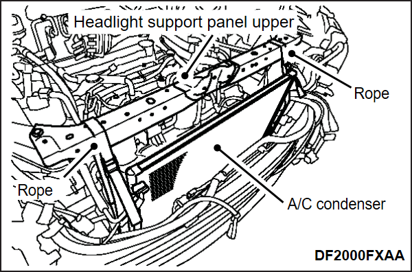
1. To prevent from falling, fix the A/C condenser to the Headlight support panel upper (Refer to TBD - Loose Panel [Loose Panel Removal and Installation]) with a rope or similar device (Body - Loose panel - REMOVAL AND INSTALLATION ).
).
 ).
).2. Remove the front suspension member (Refer to Front Suspension - Front Suspension Member) (Front suspension - Front suspension member Removal and Installation ).
).
 ).
).<<C>> LEFT ENGINE MOUNT INSULATOR / RIGHT ENGINE MOUNT INSULATOR / ENGINE, GENERATOR, FRONT MOTOR AND FRONT TRANSAXLE ASSEMBLY REMOVAL
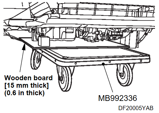
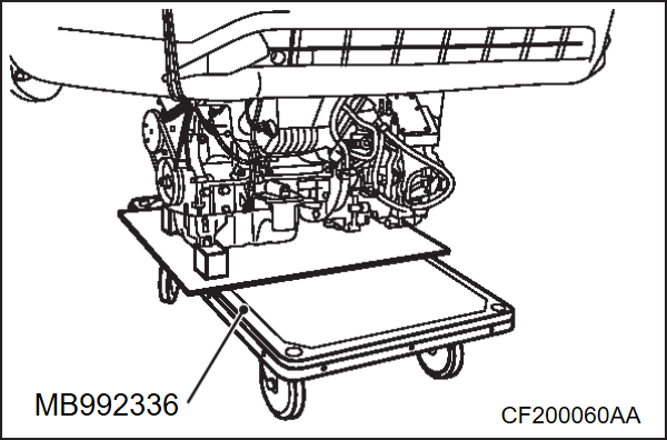
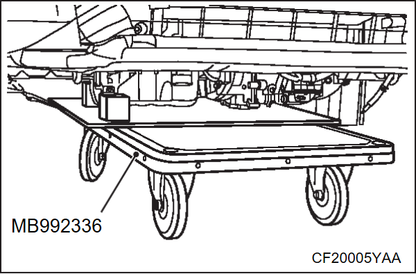
1. Place special tool EV battery cart (MB992336) below the assembly (which consists of the engine, the generator, the front motor and the front transaxle).
2.
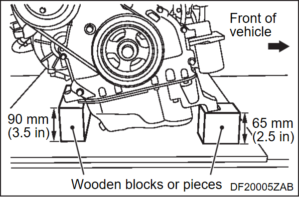
| caution | Always use wooden blocks or pieces to take the weight of the assembly at the specified position. If the weight is taken by the bottom of the oil pan, it will be deformed. |
Place wooden blocks or pieces so that the weight of the assembly is taken at the position shown in the figure.
3. Lower the lift to a position where the weight of the engine, generator, front motor and front transaxle assembly is not placed on the left engine mount insulator and the right engine mount insulator.
4. Remove each of the mounting bolts and nuts from the left engine mount insulator and the right engine mount insulator.
5. Remove the left engine mount insulator and the right engine mount insulator.
6. Make sure that all the hoses and wiring harness connectors are disconnected.
7.
| caution | Be careful not to bend the fuel-high pressure hose. |
Raise the body slowly with a lift, and remove the assembly. Raise the vehicle body slowly using a lift, then remove the assembly of the engine, generator, front motor and front transaxle.
INSTALLATION SERVICE POINT
>>A<< ENGINE, GENERATOR, FRONT MOTOR AND FRONT TRANSAXLE ASSEMBLY / RIGHT ENGINE MOUNT INSULATOR / LEFT ENGINE MOUNT INSULATOR INSTALLATION
1.
| caution | Always use wooden blocks or pieces to take the weight of the assembly (which consists of the engine, the generator, the front motor and the front transaxle) at the specified position. If the weight is taken by the bottom of the oil pan, it will be deformed. |
Place wooden blocks or pieces so that the weight of the assembly is taken at the position shown in the figure.
2. Place the assembly on special tool EV battery cart (MB992336) below the lifted vehicle.
3. Checking that the hose and harness connector, etc. are not getting trapped, lower the lift to a position where the right engine mount insulator and the left engine mount insulator can be installed.
4. Install the right engine mount insulator (Refer to Power plant mount - Removal and Installation ).
).
 ).
).5. Install the left engine mount insulator (Refer to Power plant mount - Removal and Installation ).
).
 ).
).![[Previous]](../../../buttons/fprev.png)
![[Next]](../../../buttons/fnext.png)
