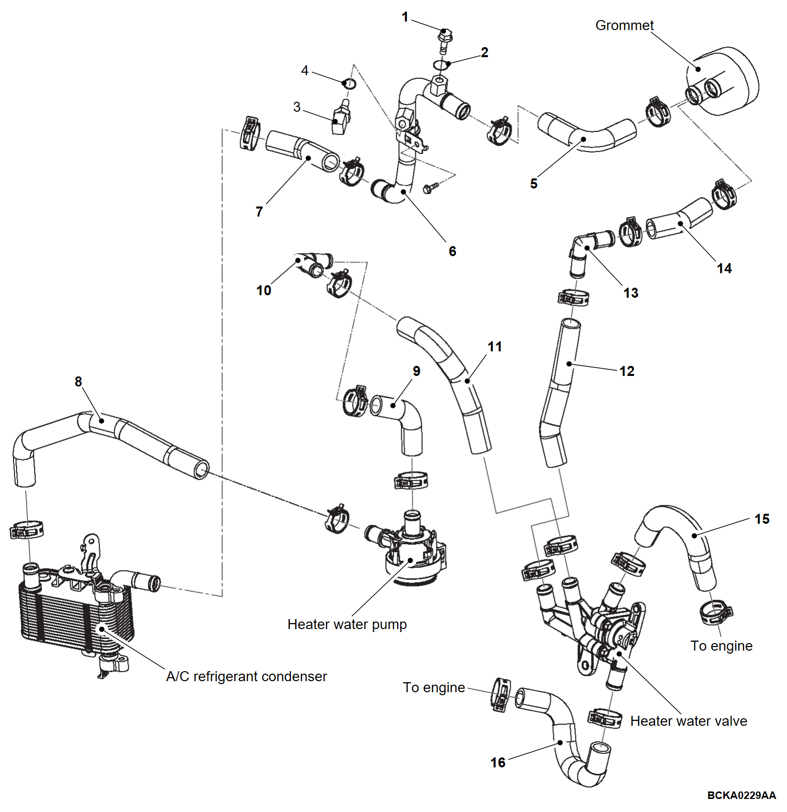
Removal and Installation
Pre-removal and post-installation operation
|
REMOVAL SERVICE POINT
INSTALLATION SERVICE POINTS
>>A<< HEATER HOSE / JOINT HOSE CONNECTION
<JOINT HOSE>
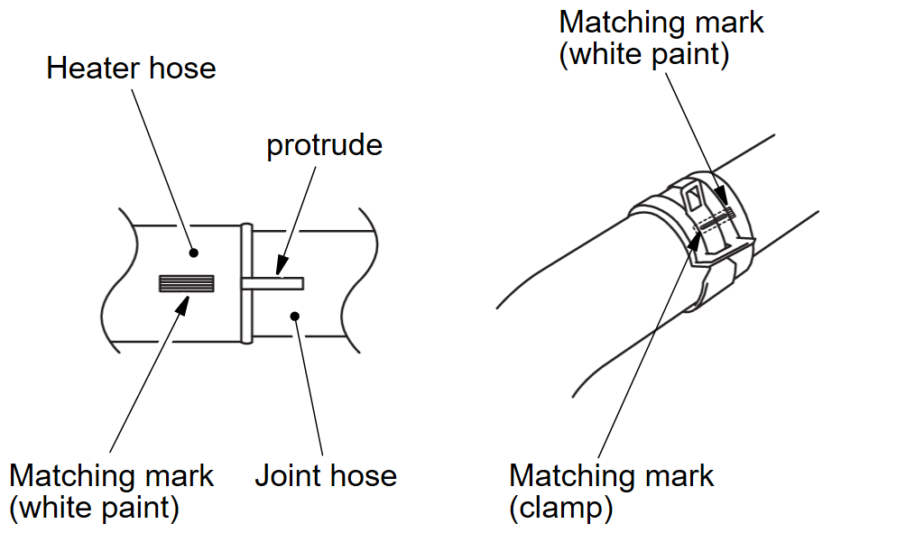
1. Insert the heater hose to the protruding section of the joint hose and align the matching mark (white paint) of the heater hose to the protruding section.
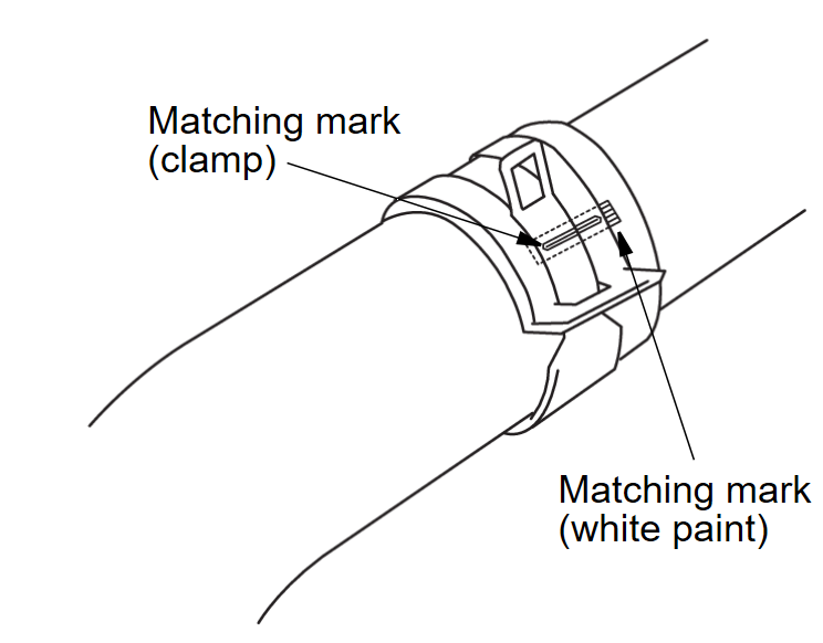
2. Align the matching mark that was drawn on the hose clamp when disconnecting with the matching mark on the heater hose, and attach the hose clamp.
<EXCEPT JOINT HOSE>
Align the matching mark that was drawn on the hose clamp when disconnecting with the matching mark on the heater hose, and attach the hose clamp.
![[Previous]](../../../buttons/fprev.png)
![[Next]](../../../buttons/fnext.png)


