[Previous][Next]
Removal and Installation
 
 
caution
  • Disconnect the 12V battery (-) terminal and wait for 60 seconds or more before starting work. Insulate the disconnected (-) terminal by wrapping a tape.
  • The parts indicated by * indicates parts which should be temporarily tightened, and then fully tightened with the vehicle standing on the ground at curb weight.
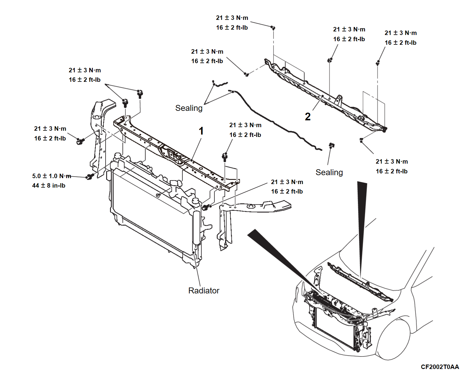
Headlight support upper panel removal steps
Secondary lever, Hood lock (Refer to REMOVAL AND INSTALLATION)
Crash zone sensor (Refer to Crash zone sensor Removal and Installation)
Radiator support upper insulator (Refer to Radiator RADIATOR REMOVAL AND INSTALLATION)
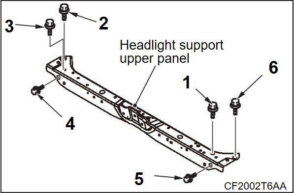
1.Headlight support upper panel
Cowl top panel removal steps
Front wiper drive assembly (Refer to Front wiper Removal and Installation)
2.Cowl top panel
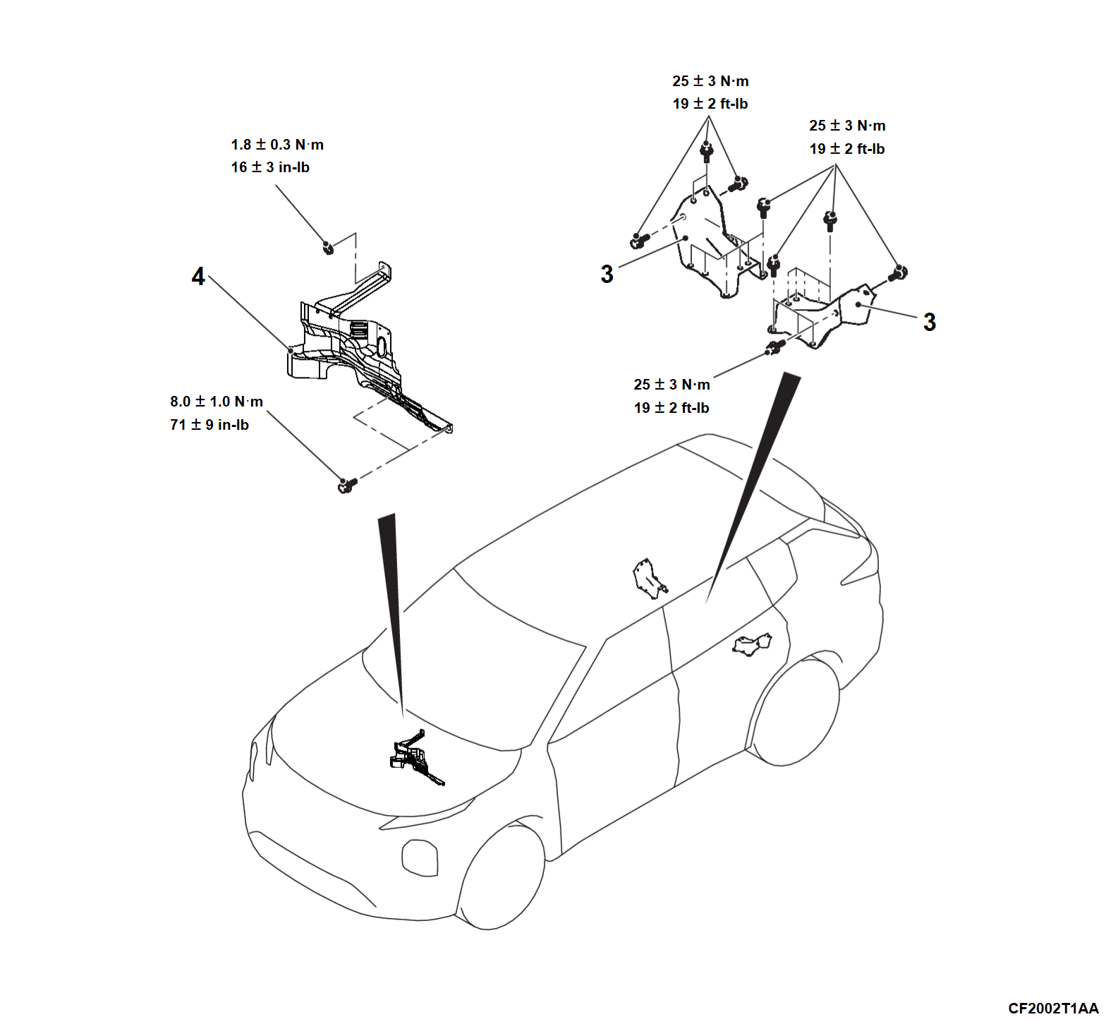
Rear wheelhouse inner panel brace removal steps
Luggage side lower finisher (Refer to Luggage TrimRemoval and Installation)
3.Rear wheelhouse inner panel brace
Dash panel heat protector removal steps
Front wiper drive assembly (Refer to Front wiper Removal and Installation)
2.Cowl top panel
4.Dash panel heat protector
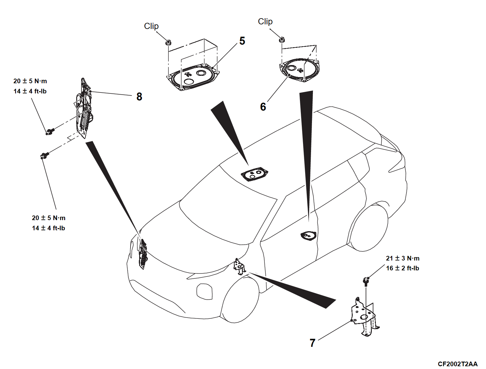
Rear floor hole cover removal steps
Second Seat Cushion Assembly (Refer to Second seat assembly Removal and Installation)
5.Rear floor hole cover(RH)
6.Rear floor hole cover(LH)
Front sidemember bracket removal steps
Power unit removal steps
7.Front sidemember bracket
Front end side reinf assembly removal steps
8.Front end side reinf assembly
 
 
INSTALLATION SERVICE POINTS
 
 
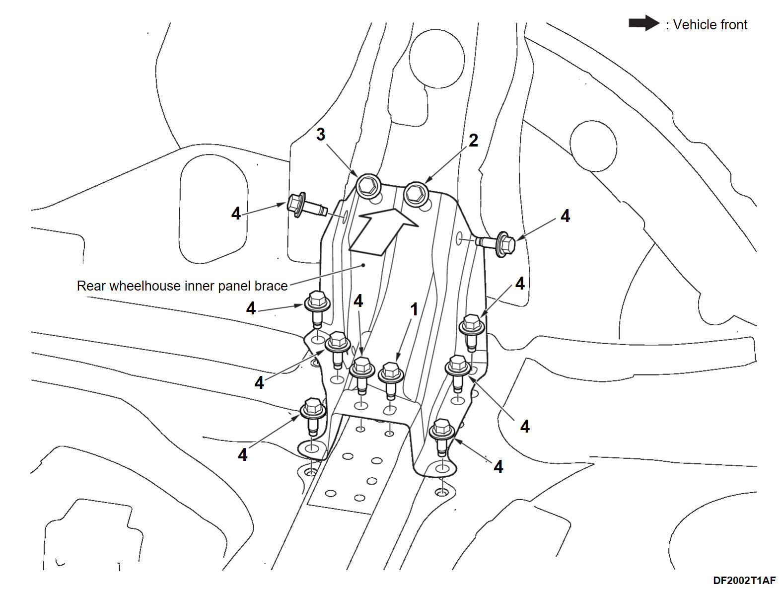
>>A<< REAR WHEELHOUSE INNER PANEL BRACE INSTALLATION
1.
Temporarily hand tighten the bolt 1.
2. Press the rear wheelhouse inner panel brace toward the fastening surface of the bolt 2 and 3, clear the gap between the rear wheelhouse inner panel brace and the rear wheelhouse inner panel, and tighten the bolt 2 and 3 with 25 ± 3 N·m (19 ± 2 ft-lb).
3. Temporarily hand tighten the bolt 4 (9 places), and check whether the gap between the surface of the rear floor and the rear wheelhouse inner panel brace is cleared.
cautionIf the gap between the surface of the rear floor and the rear wheelhouse inner panel brace is not cleared, repeat the step 2.
4. Tighten the bolt 1 and the bolt 4 (9 places) with 25 ± 3 N·m (19 ± 2 ft-lb).


>>B<< HEADLIGHT SUPPORT UPPER PANEL INSTALLATION
Tighten the headlight support upper panel bolts in the numerical order to 21 ± 3 N·m (16 ± 2 ft-lb).