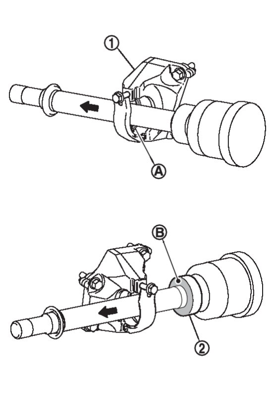
Removal and Installation
REMOVAL
Left Side
1. Remove tires. Refer to Exploded View .
.
 .
.2. Remove engine room under cover. Refer to Removal and Installation .
.
 .
.3. Remove front bumper fascia assembly. Refer to Removal and Installation .
.
 .
.4. Remove front wheel sensor from steering knuckle. Refer to Exploded View .
.
 .
.5. Remove lock plate from strut assembly. Refer to Removal and Installation .
.
 .
.6. Remove caliper assembly. Hang caliper assembly in a place where it will not interfere with work. Refer to Removal and Installation .
.
 .
.| caution | Never depress brake pedal while brake caliper is removed. |
7. Remove disc rotor. Refer to Removal and Installation .
.
 .
.8. Release stacked area of wheel hub lock nut. Refer to Removal and Installation .
.
 .
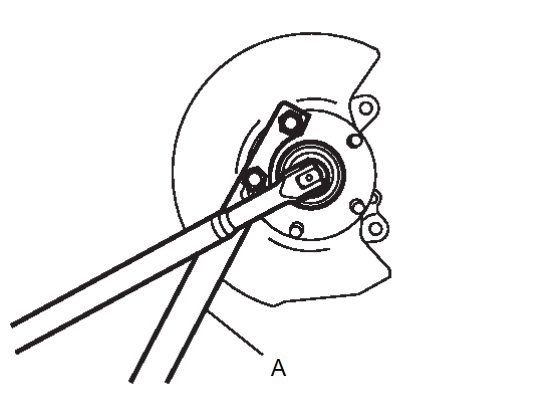
.9. Loosen wheel hub lock nut using a hub lock nut wrench (A) (SST: KV40104000). Refer to Removal and Installation .
.
 .
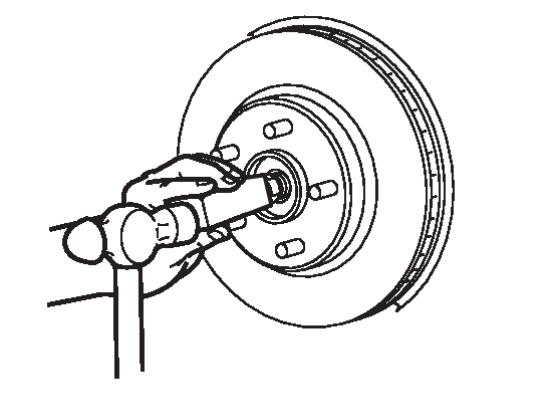
.10. Patch hub lock nut with a piece of wood. Hammer the wood to disengage wheel hub from drive shaft.
| caution |
|
| note | Use suitable puller, if wheel hub and bearing assembly and drive shaft cannot be separated even after performing the above procedure. |
11. Remove wheel hub lock nut.
12. Separate steering outer socket from steering knuckle. Refer to Removal and Installation .
.
 .
.13. Lower the front suspension member by approximately 15 mm (0.6 in) to separate the connection of the transverse link and the steering knuckle (lower side). Refer to Removal and Installation .
.
 .
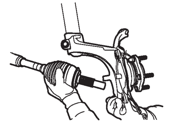
.14. Remove drive shaft from wheel hub and bearing assembly.
| caution |
|
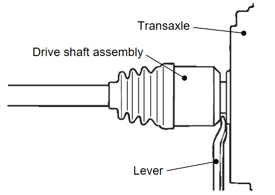
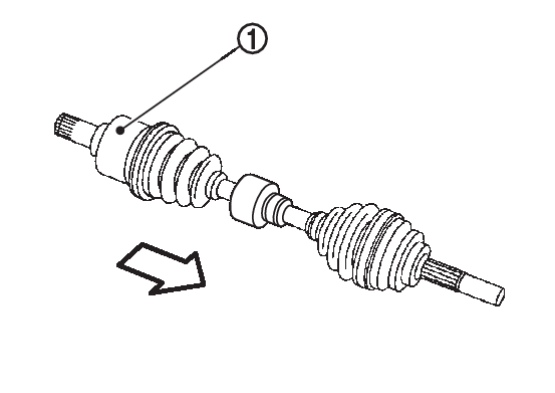
15. Remove drive shaft from transaxle assembly.
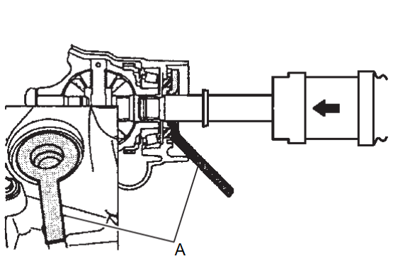
- Insert a lever between the transaxle case and drive shaft assembly, and then pull the drive shaft assembly out from the transaxle.
caution - Never pull out the drive shaft assembly from the wheel side. Otherwise, the transaxle side joint assembly may be damaged. Always pull out from the transaxle side with a lever.
- Care must be taken to ensure that the oil seal of the transaxle is not damaged by the spline part of the drive shaft assembly.
- Never place drive shaft joint at an extreme angle when removing drive shaft.
- Be careful not to overextend slide joint.
- Confirm that the circular clip is attached to the drive shaft.
Right Side
1. Remove tires. Refer to Exploded View .
.
 .
.2. Remove engine room under cover. Refer to Removal and Installation .
.
 .
.3. Remove front bumper fascia assembly. Refer to Removal and Installation .
.
 .
.4. Remove front wheel sensor from steering knuckle. Refer to Exploded View .
.
 .
.5. Remove lock plate from strut assembly. Refer to Removal and Installation .
.
 .
.6. Remove caliper assembly. Hang caliper assembly in a place where it will not interfere with work. Refer to Removal and Installation .
.
 .
.| caution | Never depress brake pedal while brake caliper is removed. |
7. Remove disc rotor. Refer to Removal and Installation .
.
 .
.8. Release stacked area of wheel hub lock nut. Refer to Removal and Installation .
.
 .
.9. Loosen wheel hub lock nut using a hub lock nut wrench (A) (SST: KV40104000). Refer to Removal and Installation .
.
 .
.10. Patch hub lock nut with a piece of wood. Hammer the wood to disengage wheel hub from drive shaft.
| caution |
|
| note | Use suitable puller, if wheel hub and bearing assembly and drive shaft cannot be separated even after performing the above procedure. |
11. Remove wheel hub lock nut.
12. Separate steering outer socket from steering knuckle. Refer to Removal and Installation .
.
 .
.13. Lower the front suspension member by approximately 15 mm (0.6 in) to separate the connection of the transverse link and the steering knuckle (lower side). Refer to Removal and Installation .
.
 .
.14. Remove drive shaft from wheel hub and bearing assembly.
| caution |
|
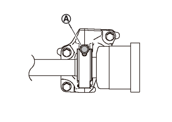
15. If necessary, remove the catalyst bracket, support bearing bracket mounting bolts and the support bearing bracket.
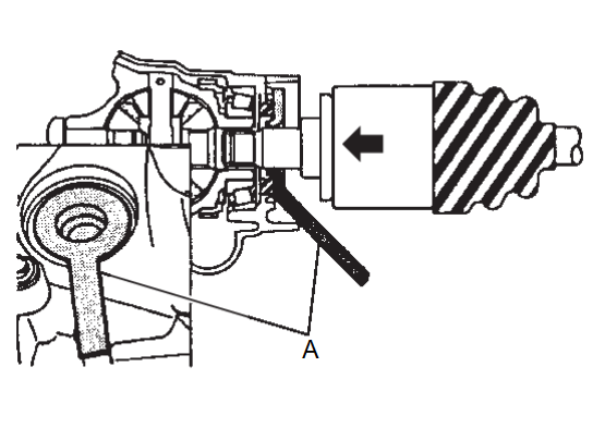
16. Remove drive shaft from transaxle assembly.
| caution |
|
INSTALLATION
Left Side
Note the following, and install in the reverse order of removal.
| caution | Always replace transaxle side oil seal with new one when installing drive shaft. Refer to DISASSEMBLY AND ASSEMBLY . . |
- To prevent damage to the oil seal of the transaxle side when inserting the drive shaft, place protector (A) (SST: KV38107900) to the oil seal part before inserting it, and remove the protector, slide the drive shaft and install it securely.
warning Ensure that circular clip is properly engaged, otherwise the housing assembly could pull away from transaxle during vehicle operation resulting in loss of drive force and possible drive shaft damage, which may cause a crash and serious injury or damage the drive shaft. caution - To ensure the circular clip is properly engaged, grasp the housing
 and pull back and forth in axial direction while listening for clicking sounds.
: Wheel side - Pull the wheel side joint part in the axial direction away from transaxle assembly (arrow). Confirm that the wheel side joint part cannot be pulled out.
- To ensure the circular clip is properly engaged, grasp the housing
- Clean the matching surface of wheel hub lock nut and wheel hub and bearing assembly.
caution Never apply lubricating oil to these matching surface. - Clean the matching surface of drive shaft and wheel hub and bearing assembly. And then apply grease [service parts (MS991241)] to surface
 of wheel side joint part of drive shaft.
caution Apply grease to cover entire flat surface of wheel side joint part of drive shaft. Amount grease : 1.0 – 3.0 g (0.04 – 0.10 oz) - Insert drive shaft to wheel hub, and then temporarily tighten hub lock nut.
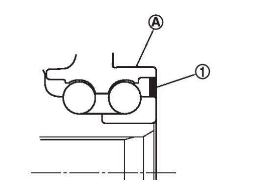
caution - The wheel speed detection magnetic encoder collects metallic particles easily, because it is magnetized. Make sure that the magnetic encoder does not collect metallic particles.
- When removing the drive shaft from the wheel hub and bearing assembly
 , make sure that it does not contact with the wheel speed detection magnetic encoder (integrated with the inner oil seal)
  to avoid damage.
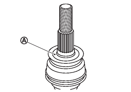
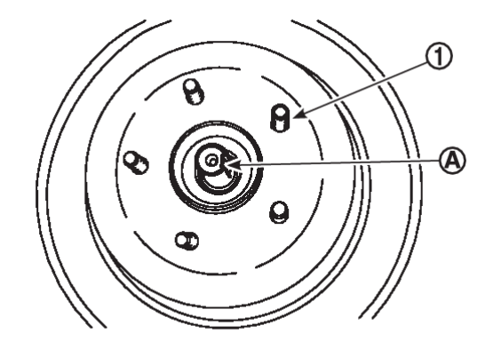
 - Never overlap drive shaft stacked area
 and wheel hub bolts
  .
.
- Tighten the wheel hub lock nut to the specified torque.

: 240.0 – 270.0 N·m (24.5 – 27.6 kg-m, 177.1 – 199.1 ft-lb) caution - Since the drive shaft is assembled by press-fitting, use the tightening torque range for the wheel hub lock nut.
- Be sure to use torque wrench to tighten the wheel hub lock nut. Never use a power tool.
- Never reuse wheel hub lock nut.
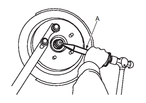
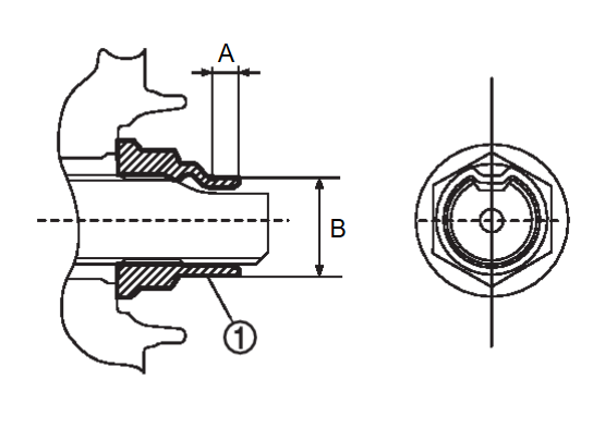
note Wheel hub lock nut tightening torque does not over torque for avoiding axle noise, and does not less than torque for avoiding looseness. - Using lock nut crimp punch (SST: KV40108700) (A), stake wheel hub lock nut and drive shaft staked area.
note Use the following range for stacking the wheel hub lock nut  .
.A : 6.2 mm (0.244 in) B : 26.4 – 27.8 mm (1.039 – 1.094 in)
Right Side
Note the following, and install in the reverse order of removal.
| caution | Always replace transaxle side oil seal with new one when installing drive shaft. Refer to DISASSEMBLY AND ASSEMBLY . . |
- To prevent damage to the oil seal of the transaxle side when inserting the drive shaft, place protector (A) (SST: KV38107900) to the oil seal part before inserting it, and remove the protector, slide the drive shaft and install it securely.
caution Never reuse transaxle side oil seal.
- Install the drive shaft securely to the support bearing bracket as follows.
- Clean the matching surface of wheel hub lock nut and wheel hub and bearing assembly.
caution Never apply lubricating oil to these matching surface. - Clean the matching surface of drive shaft and wheel hub and bearing assembly. And then apply grease [service parts (MS991241)] to surface
 of wheel side joint part of drive shaft.
caution Apply grease to cover entire flat surface of wheel side joint part of drive shaft. Amount grease : 1.0 – 3.0 g (0.04 – 0.10 oz) - Insert drive shaft to wheel hub, and then temporarily tighten hub lock nut.
caution - The wheel speed detection magnetic encoder collects metallic particles easily, because it is magnetized. Make sure that the magnetic encoder does not collect metallic particles.
- When removing the drive shaft from the wheel hub and bearing assembly
 , make sure that it does not contact with the wheel speed detection magnetic encoder (integrated with the inner oil seal)
  to avoid damage.
 - Never overlap drive shaft stacked area
 and wheel hub bolts
  .
.
- Tighten the wheel hub lock nut to the specified torque.

: 240.0 – 270.0 N·m (24.5 – 27.6 kg-m, 177.1 – 199.1 ft-lb) caution - Since the drive shaft is assembled by press-fitting, use the tightening torque range for the wheel hub lock nut.
- Be sure to use torque wrench to tighten the wheel hub lock nut. Never use a power tool.
- Never reuse wheel hub lock nut.
note Wheel hub lock nut tightening torque does not over torque for avoiding axle noise, and does not less than torque for avoiding looseness. - Using lock nut crimp punch (SST: KV40108700) (A), stake wheel hub lock nut and drive shaft staked area.
note Use the following range for stacking the wheel hub lock nut  .
.A : 6.2 mm (0.244 in) B : 26.4 – 27.8 mm (1.039 – 1.094 in)
![[Previous]](../../../buttons/fprev.png)
![[Next]](../../../buttons/fnext.png)
 of the support bearing
  .
.