Removal and Installation
REMOVAL
1. Remove tires. Refer to Exploded View .
.
 .
.2. Remove engine room under cover. Refer to Removal and Installation .
.
 .
.3. Remove front bumper fascia assembly. Refer to Removal and Installation .
.
 .
.4. Remove front wheel sensor from steering knuckle. Refer to Exploded View .
.
 .
.5. Remove lock plate from strut assembly. Refer to Removal and Installation .
.
 .
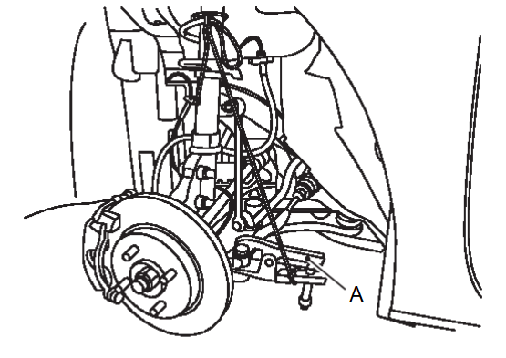
.6. Remove brake caliper assembly. Hang brake caliper assembly in a place where it will not interfere with work. Refer to Removal and Installation .
.
 .
.| caution | Never depress brake pedal while brake caliper is removed. |
7. Remove disc rotor.
| caution |
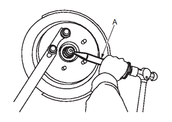
8. Using lock nut chisel (SST: KV40108800) (A), release stacked area of wheel hub lock nut.
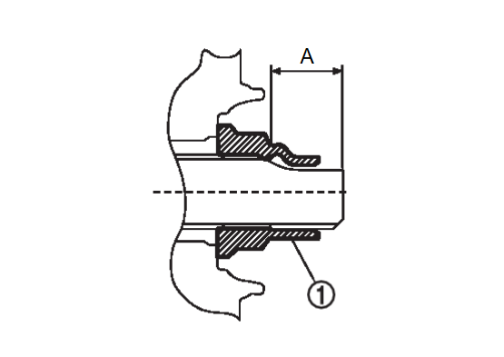
| note | Stacked area is approximately 20.5 mm (0.81 in) (A) of wheel hub lock nut  . . |
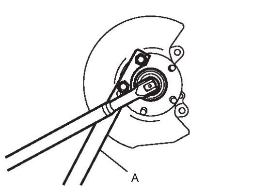
9. Loosen wheel hub lock nut, using a hub lock nut wrench (SST: KV40104000) (A).
| caution |
|
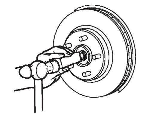
10. Patch wheel hub lock nut with a piece of wood. Hammer the wood to disengage wheel hub from drive shaft.
| caution |
|
| note | Use suitable puller, if wheel hub and drive shaft cannot be separated even after performing the above procedure. |
11. Remove wheel hub lock nut.
12. Remove wheel hub and bearing assembly and splash guard.
13. Remove steering outer socket from steering knuckle so as not to damage ball joint boot using a ball joint remover (A) (commercial service tool).
| caution |
|
14. Remove front stabilizer connecting rod.
15. Remove transverse link mounting bolts and nuts (lower side). Refer to Removal and Installation .
.
 .
.16. Separate the connection of transverse link and steering knuckle (lower side) as follows.
(1) Separate the connection of steering gear assembly and steering column assembly. Refer to Removal and Installation .
.
 .
.(2) Remove torque rod. Refer to Removal and Installation .
.
 .
.(3) Remove the exhaust front pipe. Refer to EXHAUST PIPE AND MAIN MUFFLER REMOVAL AND INSTALLATION .
.
 .
.(4) Disconnect the ambient sensor connector. Refer to Removal and Installation .
.
 .
.(5) Remove the air guide grill mounting nuts and clips, and then remove the air guide grill. Refer to Removal and Installation .
.
 .
.(6) To prevent the radiator assembly and condenser assembly from falling off, secure them to the headlight support panel upper with a rope or the like.
(7) Remove the electric oil pump mounting bolts and separate them from the electric oil pump bracket. Refer to ELECTRIC OIL PUMP REMOVAL AND INSTALLATION .
.
 .
.| note | Do not remove the electric oil pump bracket from the front suspension member. |
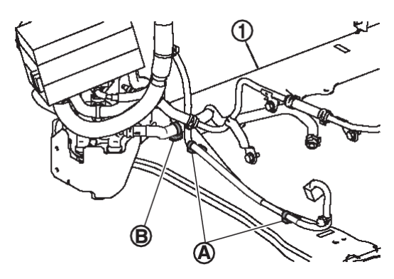
(8) Remove the harness clips  and the EV oil cooler hose clip
  on the left side of the front suspension member
  .
.
 and the EV oil cooler hose clip
  on the left side of the front suspension member
  .
.(9) Set suitable jack under front suspension member.
| caution |
|
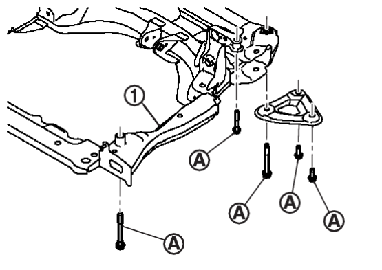
(10) Loosen the front suspension member mounting bolts  to lower the front suspension member
  by approximately 15 mm (0.6 in). Refer to Exploded View
 .
.
 to lower the front suspension member
  by approximately 15 mm (0.6 in). Refer to Exploded View
 .
.(11) Gradually lower the jack to lower the front suspension member by approximately 15 mm (0.6 in).
(12) Separate the transverse link from the steering knuckle while taking care not to damage the ball joint boot.
17. Remove cowl top cover. Refer to Removal and Installation .
.
 .
.18. Separate the connection of front strut assembly and steering knuckle as follows.
| caution | Be sure to keep the following procedure because steering knuckle may be damaged when you enlarge the gap of steering knuckle too much. |
(1) Remove strut mounting bolt and nut from steering knuckle.
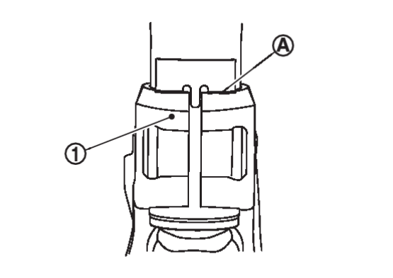
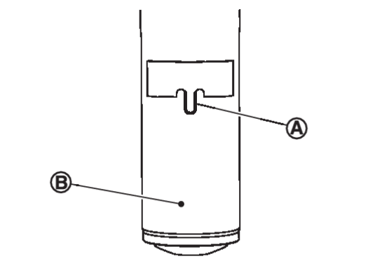
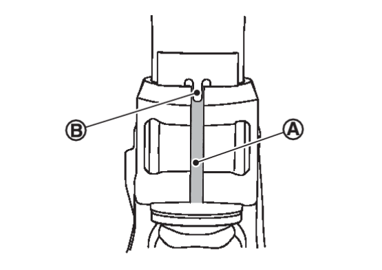
(2) Measure the gap (A) of the steering knuckle. And then mark the enlarged limit (B) to the chisel (commercial service tool).
 | Marking |
| Enlarged limit (B) = gap (A) + 2.5 mm (0.098 in) |
| note | Standard of gap: 6.9 ± 0.5 mm (0.272 ± 0.020 in) |
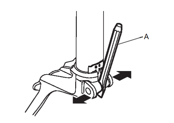
(3) Enlarge the gap of the steering knuckle with the chisel (A) (commercial service tool) not to surpass a limit as shown in the figure.
| caution |
(4) Separate the connection of strut assembly and steering knuckle.
| caution |
|
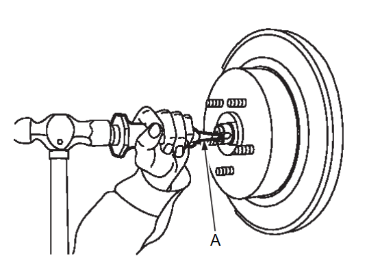
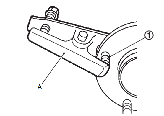
19. Remove hub bolts  from wheel hub, using the ball joint remover (commercial service tool) (A).
 from wheel hub, using the ball joint remover (commercial service tool) (A).
 | caution |
|
20. Perform inspection after removal. Refer to InspectionInspection .
.
 .
.INSTALLATION
Note the following, and install in the reverse order of the removal.
Hub Bolts
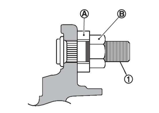
Place a washer  as shown in the figure to install the hub bolts
  by using the tightening force of the nut
  .
.
 as shown in the figure to install the hub bolts
  by using the tightening force of the nut
  .
.| caution |
|
Drive shaft
- Clean the matching surface of wheel hub lock nut and wheel hub.
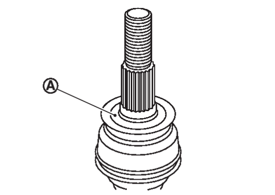
caution Never apply lubricating oil to these matching surface. - Clean the matching surface of drive shaft, wheel hub, and wheel bearing. And then apply grease [service parts (MS991241)] to surface
 of wheel side joint part of drive shaft.
caution Apply grease to cover entire flat surface of wheel side joint part of drive shaft. Amount grease 1.0 – 3.0 g (0.04 – 0.10 oz) - When installing drive shaft to wheel hub.
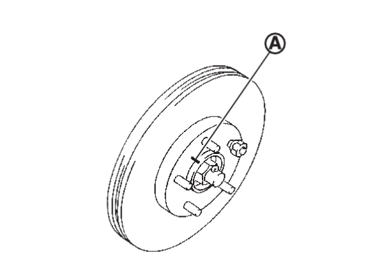
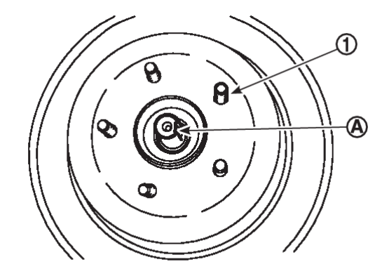
caution Never overlap drive shaft stacked area  and hub bolts
  .
. - Use the following torque range for tightening the wheel hub lock nut.

: 240.0 – 270.0 N·m (24.5 – 27.6 kg-m, 177.1 – 199.1 ft-lb) caution - Since the drive shaft is assembled by press-fitting, use the tightening torque range for the wheel hub lock nut.
- Be sure to use torque wrench to tighten the wheel hub lock nut. Never use a power tool.
- Never reuse wheel hub lock nut.
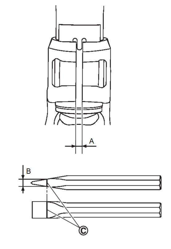
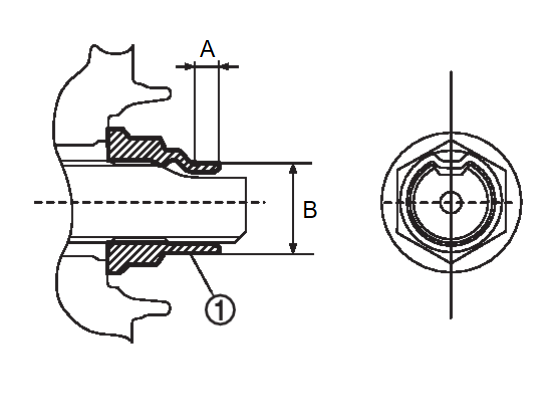
note Wheel hub lock nut tightening torque does not over torque for avoiding axle noise, and does not less than torque for avoiding looseness. - Using lock nut crimp punch (SST: KV40108700) (A), stake wheel hub lock nut and drive shaft staked area.
note Use the following range for stacking the wheel hub lock nut  .
.A : 6.2 mm (0.244 in) B : 26.4 – 27.8 mm (1.039 – 1.094 in)
Disc rotor
| caution |
Strut Assembly and Steering Knuckle Connection
| caution | Be sure to remove lubricants if lubricant has been used to separate the connection of strut assembly and steering knuckle. |
Install the steering knuckle to strut assembly as follows.
1. Set suitable jack under steering knuckle.
![[Previous]](../../../buttons/fprev.png)
![[Next]](../../../buttons/fnext.png)
 until contacts stopper bracket