Removal and Installation
| danger | PHEV vehicles have high voltage batteries, so incorrect handling may cause electric shock and electric leakage. Work correctly, according to the work procedure, when performing inspection and maintenance. |
| warning |
|
| caution |
|
REMOVAL
Outline
Without disconnecting the A/C piping, lower the assembly (which consists of the engine, the generator, the front motor and the front transaxle assembly) slightly to the lower side of the vehicle, and remove the engine mounting insulators (LH and RH) from the gap.
Preparation
1. Release the fuel pressure in the fuel line. Refer to FUEL PUMP CONNECTOR DISCONNECTION (HOW TO REDUCE PRESSURIZED FUEL PRESSURE) .
.
 .
.2. Shut off the high-voltage circuit. Refer to PRECAUTIONS ON HOW TO USE THE HIGH-VOLTAGE VEHICLE .
.
 .
.3. Check the voltage of the high-voltage circuit. Refer to PRECAUTIONS ON HOW TO USE THE HIGH-VOLTAGE VEHICLE .
.
 .
.4. Drain the engine coolant. Refer to ENGINE COOLANT REPLACEMENT .
.
 .
.5. Drain the EV coolant. Refer to EV COOLANT CHANGE .
.
 .
.6. Drain the engine oil. Refer to ENGINE OIL CHANGE .
.
 .
.7. Drain the EV oil. Refer to OIL CHANGE .
.
 .
.8. Drain the front transaxle fluid. Refer to TRANSAXLE FLUID CHANGE .
.
 .
.9. Remove the following parts.
- Front road wheels and tires: Refer to Exploded View
 .
. - Engine room under cover: Refer to Removal and Installation
 .
. - Fender protector: Refer to REMOVAL AND INSTALLATION
 .
. - Engine room side cover: Refer to Removal and Installation
 .
. - Exhaust front pipe: Refer to EXHAUST PIPE AND MAIN MUFFLER REMOVAL AND INSTALLATION
 .
. - Front bumper fascia assembly: Refer to Removal and Installation
 .
. - Air cleaner intake duct, air cleaner assembly and air cleaner bracket front: Refer to AIR CLEANER REMOVAL AND INSTALLATION
 .
. - Engine Control Module (ECM): Refer to ENGINE CONTROL MODULE (ECM) REMOVAL AND INSTALLATION
 .
. - Power drive unit: Refer to POWER DRIVE UNIT REMOVAL AND INSTALLATION
 .
. - EV oil cooler: Refer to EV OIL COOLER REMOVAL AND INSTALLATION
 .
. - EV radiator: Refer to EV RADIATOR/EV RADIATOR CONDENSER TANK REMOVAL AND INSTALLATION
 .
. - Separate the connection of steering gear assembly and steering column assembly.: Refer to Removal and Installation
 .
.
Engine Room LH
1. Disconnect all the connection destinations such as the engine control wiring harness around the engine mounting insulator (LH), and temporarily fix the engine control wiring harness to the engine assembly side.
| caution | Protect the connector with a plastic bag, etc. to prevent foreign matter from adhering to it during work. |
2. Remove the ground cable from the generator assembly.
Engine Room RH
1. Remove the A/C compressor assembly together with the hose from the bracket. Refer to Removal and Installation .
.
 .
.2. Tie the removed A/C compressor assembly in a place where it will not be a hindrance when removing and installing the assembly (which consists of the engine, the generator, the front motor and the front transaxle).
3. Disconnect the reservoir tank hose B from the reservior tank pipe. Refer to RADIATOR REMOVAL AND INSTALLATION .
.
 .
.Engine Room Center
1. Disconnect the radiator upper hose from the thermostat case and the radiator lower hose from the water inlet fitting. Refer to WATER HOSE AND WATER PIPE REMOVAL AND INSTALLATION .
.
 .
.2. Remove the radiator assembly. Refer to RADIATOR REMOVAL AND INSTALLATION .
.
 .
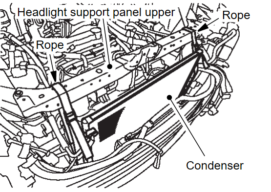
.3. Temporarily install the headlight support panel upper that was removed when the radiator was removed. Secure the A/C condenser assembly together with the A/C piping to the headlight support panel upper with a rope or the like.
4. Remove the front side air guide, the rear side air guide, the air guide lower and the air guide panel. Refer to Removal and Installation .
.
 .
.5. Disconnect the fuel-high pressure hose from the engine assembly. Refer to FUEL INJECTOR REMOVAL AND INSTALLATION .
.
 .
.6. Disconnect the heater hose from the engine assembly. Refer to Removal and Installation .
.
 .
.Vehicle Underbody
1. Remove the drive shafts (LH and RH). Refer to Removal and Installation .
.
 .
.3. Remove the front suspension member. Refer to Removal and Installation .
.
 .
.Removal
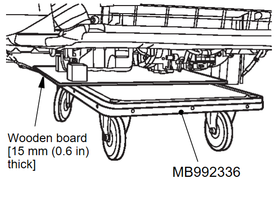
1. Place EV battery cart (SST: MB992336), with a wooden board [around 15 mm (0.6 in) thick] placed over it, under the assembly (which consists of the engine, the generator, the front motor and the front transaxle assembly).
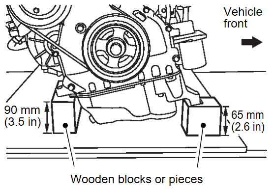
2. Place wooden blocks or pieces at the positions on the engine assembly shown in the figure (front: A/C bracket, rear: bolt head of the oil pan flange) to take the weight.
| caution | Always use wooden blocks or pieces to take the weight of the engine assembly at the specified position. If the weight is taken by the bottom of the oil pan, it will be deformed. |
3. Lower the lift until the bottom of the transaxle case touches the wooden board, taking the weight of the assembly (which consists of the engine, the generator, the front motor and the front transaxle assembly).
4. Lower the lift to a position where the weight of the assembly (which consists of the engine, the generator, the front motor and the front transaxle assembly) does not take on the engine mounting insulator (LH and RH).
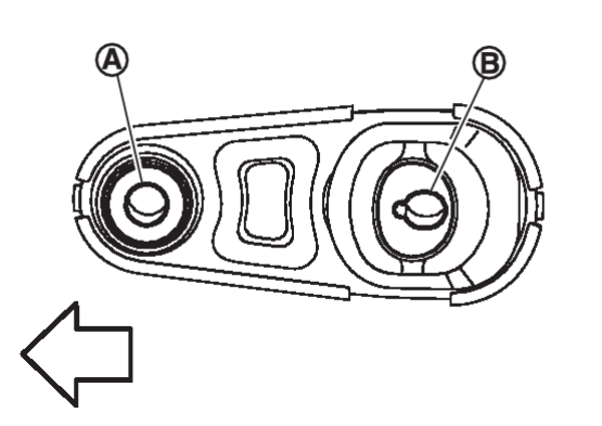
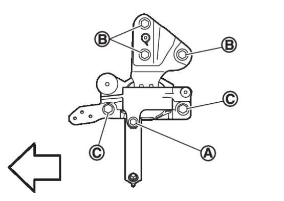
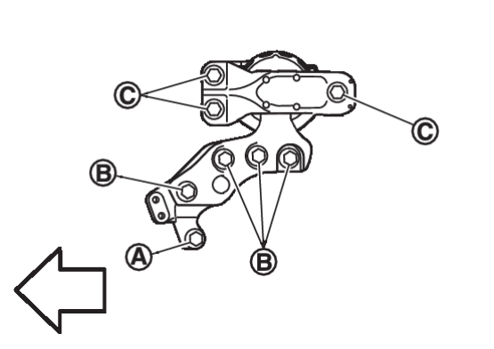
5. Remove the engine mounting stay (LH) mounting bolt  , then remove the engine mounting insulator (LH) mounting bolts
  and
and  .
.
 , then remove the engine mounting insulator (LH) mounting bolts
  and
and  .
. | : Vehicle front |
7. Make sure that all the hoses and wiring harness connectors are disconnected.
8. Raise the body slightly with a lift and remove the engine mount insulator (LH and RH) from the gap between the assembly (which consists of the engine, the generator, the front motor and the front transaxle) and the body.
| caution | Be careful not to bend the fuel-high pressure hose. |
INSTALLATION
Note the following, and install in the reverse order of removal.
| caution |
|
Preparation
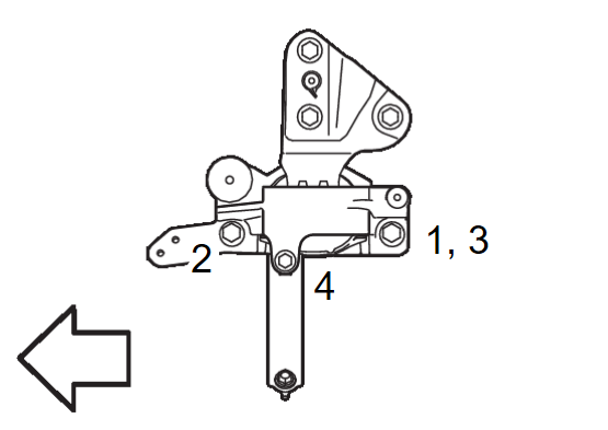
1. Install the engine mounting insulator (LH) to the vehicle, and temporarily tighten the bolts before tightening to the specified torque, referring to the tightening method and the numerical order shown below:
| Temporary tightening | : 1 |
| Final tightening (Specified torque) | : 2 → 3 → 4 |
 | : Vehicle front |
Installation
1. Lower the vehicle until the engine mounting insulator (RH) and the engine mounting insulator (LH) can be installed. To do so, be careful not to pinch the hoses or the connectors.
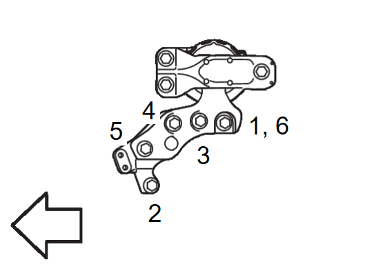
2. Install the engine mounting insulator (RH) to the engine assembly, and temporarily tighten the bolts before tightening to the specified torque, referring to the tightening method and the numerical order shown below:
| Temporary tightening | : 1 |
| Final tightening (Specified torque) | : 2 → 3 → 4 → 5 → 6 |
 | : Vehicle front |
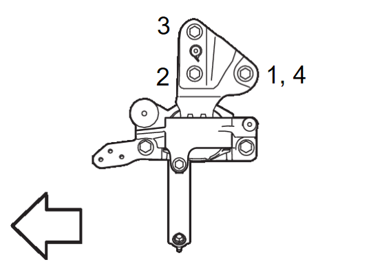
3. Install the engine mounting insulator (LH) to the front motor assembly, and temporarily tighten the bolts before tightening to the specified torque, referring to the tightening method and the numerical order shown below:
| Temporary tightening | : 1 |
| Final tightening (Specified torque) | : 2 → 3 → 4 |
 | : Vehicle front |
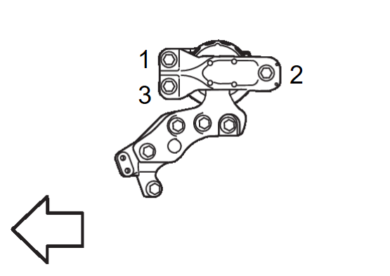
4. Tighten the engine mounting insulator (RH) mounting bolts on the vehicle side to the specified torque.
| Final tightening (Specified torque) | : 1 → 2 → 3 |
 | : Vehicle front |
| caution | Check the engine mounting insulator (LH and RH) are not twisted. |
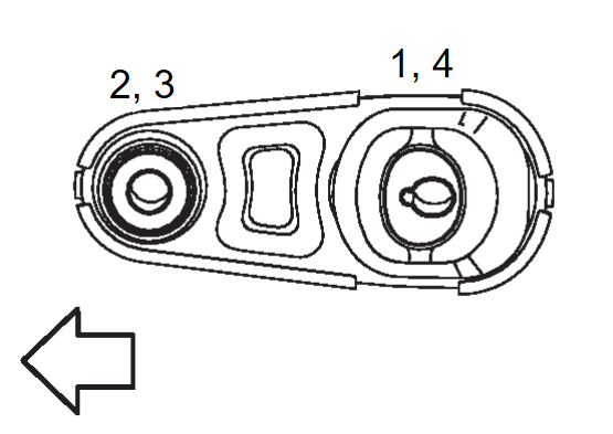
5. Install the torque rod to the front suspension member and the front transaxle torque rod adapter, and temporarily tighten the bolts before tightening to the specified torque, referring to the tightening method and the numerical order shown below:
| Temporary tightening | : 1 → 2 |
| Final tightening (Specified torque) | : 3 → 4 |
 | : Vehicle front |
| caution | Check the torque rod is not twisted. |
![[Previous]](../../../buttons/fprev.png)
![[Next]](../../../buttons/fnext.png)
