REMOVAL AND INSTALLATION
| caution |
|
Pre-removal Operation
- Remove the Cowl Top Cover (Refer to Front Wiper - Removal and Installation
 )
) - Remove the Drive Battery Cable and Clamp Bracket (Refer to Electric Motor Control Unit (EMCU) and Motor (Electeric Motor Unit) - Power Drive Unit - POWER DRIVE UNIT REMOVAL AND INSTALLATION
 )
) - Heater hose H (Heater Water Valve Side), Heater Hose I (Joint Hose A Side), Heater Hose M (Joint Hose B Side) Connection (Refer to Heater & Air Conditioning System - Removal and Installation
 )
) - Remove the Heater Water Valve (with Heater Hose M) (Refer to Heater & Air Conditioning System - Removal and Installation
 )
) - Heater Water Pump Connector Connection, Heater Water Pump Removal (Refer to Heater & Air Conditioning System - Removal and Installation
 )
) - Remove the Heater Water Pipe Assembly (Refer to Heater & Air Conditioning System - Removal and Installation
 )
) - Evaporator Outlet Temperature Sensor (Low Voltage Pipe B Side) Connector Connection (Refer to Heater & Air Conditioning System - Refrigerant Line <Vehicle with Heatpump System> - REMOVAL AND INSTALLATION
 )
) - Electric Expansion Valve (Heater Unit Side) Harness Clamp, Connector Connection (Refer to Heater & Air Conditioning System - Refrigerant Line <Vehicle with Heatpump System> - REMOVAL AND INSTALLATION
 )
) - Heater Hose H (EGR Cooler Side), Heater Hose M (Heater Water Valve Side) Connection (Refer to Heater & Air Conditioning System - Removal and Installation
 )
) - Purge Hose (Engine Side) Connection (Refer to Intake and Exhaust - INTAKE MANIFOLD REMOVAL AND INSTALLATION
 )
) - Fuel High-Pressure Hose (Engine Side) Connection (Refer to Multiport Fuel Injection System (MFI) - FUEL INJECTOR REMOVAL AND INSTALLATION
 )
)
Post-installation Operation
- Fuel High-Pressure Hose (Engine Side) Connection (Refer to Multiport Fuel Injection System (MFI) - FUEL INJECTOR REMOVAL AND INSTALLATION
 )
) - Purge Hose (Engine Side) Connection (Refer to Intake and Exhaust - INTAKE MANIFOLD REMOVAL AND INSTALLATION
 )
) - Heater Hose H (EGR Cooler Side), Heater Hose M (Heater Water Valve Side) Connection (Refer to Heater & Air Conditioning System - Removal and Installation
 )
) - Electric Expansion Valve (Heater Unit Side) Harness Clamp, Connector Connection (Refer to Heater & Air Conditioning System - Refrigerant Line - REMOVAL AND INSTALLATION
 )
) - Evaporator Outlet Temperature Sensor (Low Voltage Pipe B Side) Connector Connection (Refer to Heater & Air Conditioning System - Refrigerant Line - REMOVAL AND INSTALLATION
 )
) - Install the Heater Water Pipe Assembly (Refer to Heater & Air Conditioning System - Removal and Installation
 )
) - Heater Water Pump Connector Connection, Heater Water Pump Installation (Refer to Heater & Air Conditioning System - Removal and Installation
 )
) - Install the Heater Water Valve (with Heater Hose M) (Refer to Heater & Air Conditioning System - Removal and Installation
 )
) - Heater hose H (Heater Water Valve Side), Heater Hose I (Joint Hose A Side), Heater Hose M (Joint Hose B Side) Connection (Refer to Heater & Air Conditioning System - Removal and Installation
 )
) - Install the Drive Battery Cable and Clamp Bracket (Refer to Electric Motor Control Unit (EMCU) and Motor (Electeric Motor Unit) - Power Drive Unit - POWER DRIVE UNIT REMOVAL AND INSTALLATION
 )
) - Install the Cowl Top Cover (Refer to Front Wiper - Removal and Installation
 )
)
|
REMOVAL SERVICE POINTS
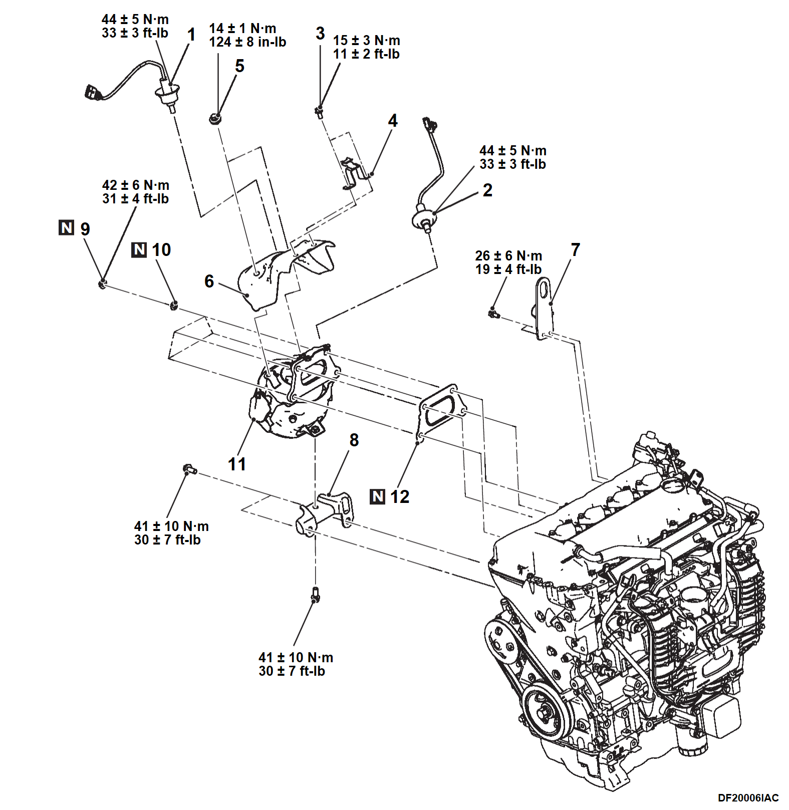
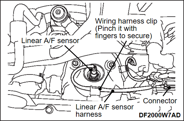
<<A>> LINEAR A/F SENSOR REMOVAL
1. Disconnect the linear A/F sensor connector and the clamp.
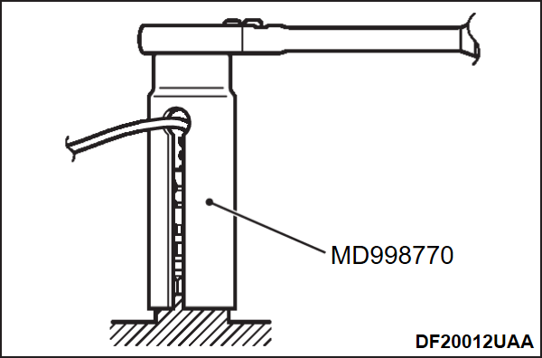
2. Remove the linear A/F sensor using the special tool linear air-fuel ratio sensor wrench (MD998770).
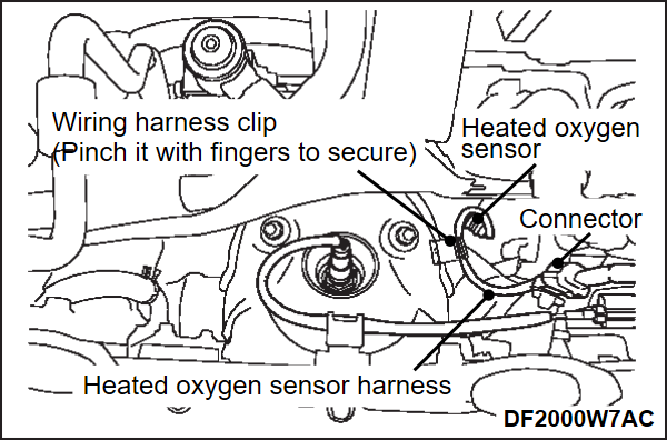
<<B>> HEATED OXYGEN SENSOR (REAR) REMOVAL
1. Disconnect the heated oxygen sensor (rear) connector and the clamp.
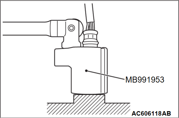
2. Remove the heated oxygen sensor (rear) using the special tool heated oxygen sensor wrench (MB991953).
INSTALLATION SERVICE POINTS
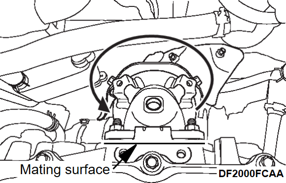
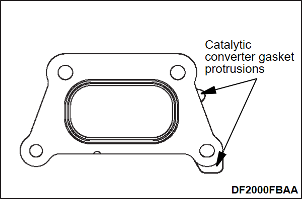
>>A<< CATALYTIC CONVERTER GASKET INSTALLATION
Install with the gasket protrusions in the direction indicated in the figure.
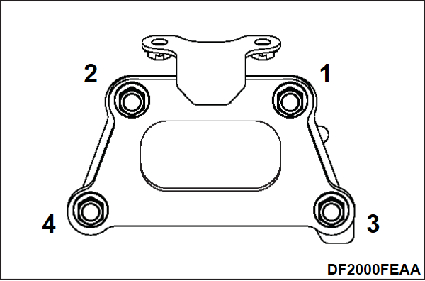
>>B<< MAIN CATALYTIC CONVERTER ASSEMBLY / CATALYTIC CONVERTER WASHER / CATALYTIC CONVERTER NUT INSTALLATION
1. Install the main catalytic converter assembly and the catalytic converter washer.
2. Temporarily tighten the catalytic converter nuts.
3. Tighten the catalytic converter nuts 1 and 2 shown in the figure to 30 N·m (22 ft-lb).
4. Following the order 3→4→1→2 in the figure, tighten the catalytic converter nuts to the specified torque.
Tightening torque: 42 ± 6 N·m (31 ± 4 ft-lb)
>>C<< CATALYTIC CONVERTER BRACKET INSTALLATION
1. After confirming that the catalytic converter bracket is in close contact with the main catalytic converter and the cylinder block, temporarily tighten the mounting bolts.
2. Tighten the bolts (two places) on the cylinder block side to the specified torque.
Tightening torque: 41 ± 10 N·m (30 ± 7 ft-lb)
3. Tighten the bolt (one place) on the main catalytic converter side to the specified torque.
Tightening torque: 41 ± 10 N·m (30 ± 7 ft-lb)
>>D<< HEATED OXYGEN SENSOR (REAR) INSTALLATION
| caution | Gather the extra wiring harness part to the sensor side and secure it with a clip. |
Tighten the heated oxygen sensor (rear) to the specified torque using a special tool heated oxygen sensor wrench (MB991953).
Tightening torque: 44 ± 5 N·m (33 ± 3 ft-lb)
![[Previous]](../../../buttons/fprev.png)
![[Next]](../../../buttons/fnext.png)
