REMOVAL AND INSTALLATION
| caution |
|
Pre-removal and Post-installation Operation
- Engine Coolant Draining and Refilling (Refer to Engine Cooling - On-Vehicle Service ENGINE COOLANT REPLACEMENT
 )
) - Air Intake Hose, Intake Duct Removal and Installation (Refer to AIR CLEANER REMOVAL AND INSTALLATION
 )
) - Front Motor (Power Unit) Cable, Generator Cable Connection [Refer to Electric Motor Control Unit (EMCU) and Motor (Electric Motor Unit) - Motor (Electric Motor Unit) <Front> - POWER DRIVE UNIT REMOVAL AND INSTALLATION
 ]
] - Throttle Body Assembly Removal and Installation (Refer to Multiport Fuel Injection (MFI) - THROTTLE BODY ASSEMBLY
 )
) - EGR Valve Removal and Installation (Refer to Engine, Motor and Emission Control - EXHAUST GAS RECIRCULATION (EGR) VALVE REMOVAL AND INSTALLATION
 )
) - EGR Cooler Removal and Installation (Refer to Engine, Motor and Emission Control - EXHAUST GAS RECIRCULATION (EGR) COOLER REMOVAL AND INSTALLATION
 )
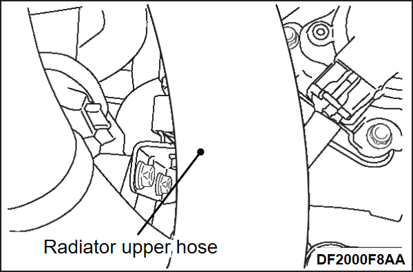
) - Radiator upper hose Removal and Installation (Refer to Engine Cooling - RADIATOR REMOVAL AND INSTALLATION
 )
)
|
REMOVAL SERVICE POINT
INSTALLATION SERVICE POINTS
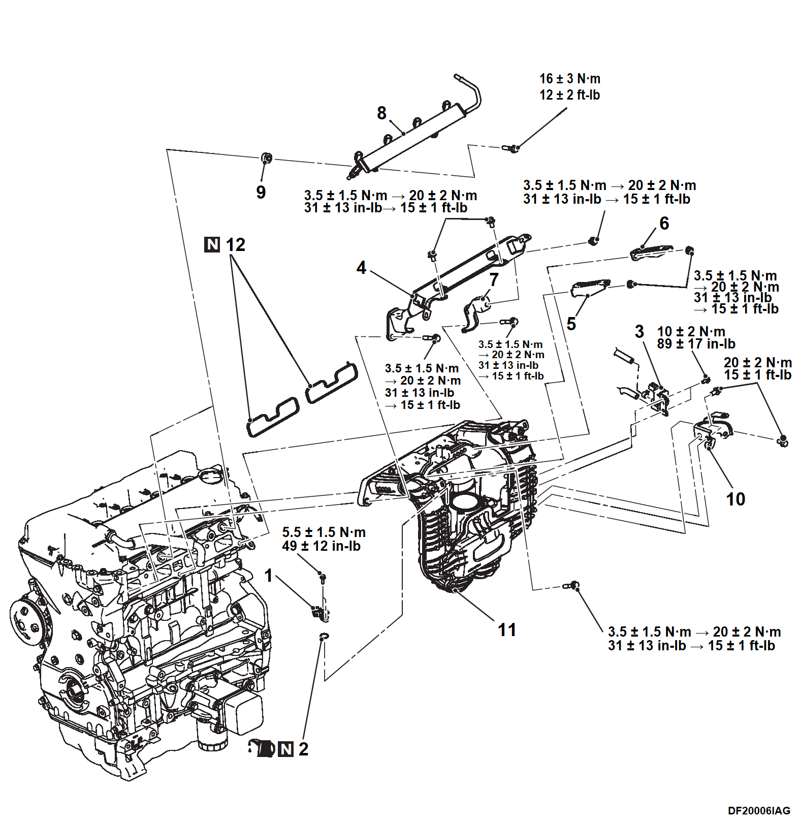
>>A<< INLET MANIFOLD / FUEL RAIL & FUEL INJECTOR ASSEMBLY / FUEL TUBE PROTECTOR STAY / FUEL TUBE PROTECTOR INSTALLATION
1. Install the fuel rail and fuel injector assembly to the specified torque.
Tightening torque: 16 ± 3 N·m (12 ± 2 ft-lb)
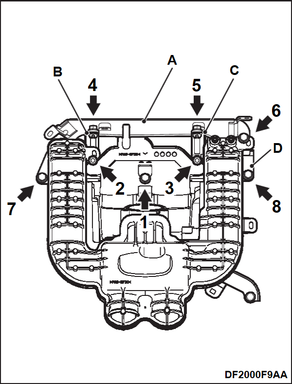
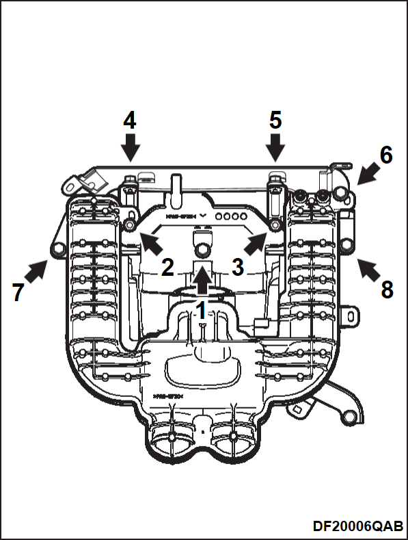
2. Temporarily tighten the inlet manifold and the parts A, B, C and D in the order shown in the figure to the specified torque.
- Part A: Fuel tube protector
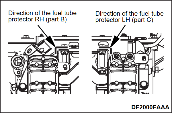
- Part B: Fuel tube protector RH
- Part C: Fuel tube protector LH
- Part D: Fuel tube protector stay
Tightening torque: 3.5 ± 1.5 N·m (31 ± 13 in-lb)
| note | When temporally tightening, check that the direction of the fuel tube protector RH (part B) and fuel tube protector LH (part C) is the same as shown in the figure. |
3. Tighten the mounting bolts and nuts to the specified torque in the numerical order as shown in the figure.
Tightening torque: 20 ± 2 N·m (15 ± 1 ft-lb)
>>B<< INLET MANIFOLD STAY INSTALLATION
1. Temporally tighten the inlet manifold stay.
2. Check that the attachment surface of the inlet manifold stay is closely attached, and tighten the mounting bolts to the specified torque.
Tightening torque: 20 ± 2 N·m (15 ± 1 ft-lb)
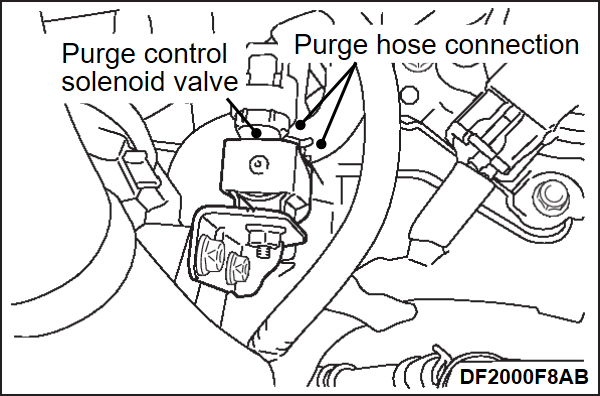
>>C<< PURGE CONTROL SOLENOID VALVE / O-RING / MANIFOLD ABSOLUTE PRESSURE SENSOR INSTALLATION
1. Apply a small amount of new engine oil to the O-ring of the manifold absolute pressure sensor.
| caution | Do not apply a force such as torsion or twist to the O-ring during assembly of the sensor and the inlet manifold. |
2. Install the manifold absolute pressure sensor and the purge control solenoid valve to the inlet manifold.
| caution | Never overtighten the mounting screws to avoid damage to the threads of inlet manifold. |
3. Tighten the manifold absolute pressure sensor to the specified torque.
Tightening torque: 5.5 ± 1.5 N·m (49 ± 12 in-lb)
| caution | Never overtighten the mounting screws to avoid damage to the threads of inlet manifold. |
4. Tighten the purge control solenoid valve to the specified torque.
Tightening torque: 10 ± 2 N·m (89 ± 17 in-lb)
![[Previous]](../../../buttons/fprev.png)
![[Next]](../../../buttons/fnext.png)
