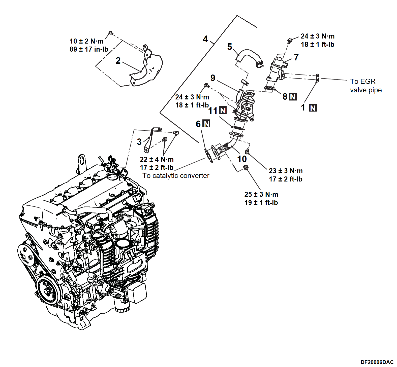
REMOVAL AND INSTALLATION
PRE-REMOVAL OPERATION
- Engine Coolant Draining (Refer to Engine Cooling - On-Vehicle Service ENGINE COOLANT REPLACEMENT
 )
) - Air Intake Hose, Intake Duct Removal (Refer to Intake exhaust - AIR CLEANER REMOVAL AND INSTALLATION
 )
) - Front Motor (Power Unit) Cable, Generator Cable Connection [Refer to Electric Motor Control Unit (EMCU) and Motor (Electric Motor Unit) - Power Drive Unit POWER DRIVE UNIT REMOVAL AND INSTALLATION
 )
) - Remove the Drive Battery Cable and Clamp Bracket (Refer to Electric Motor Control Unit (EMCU) and Motor (Electeric Motor Unit) - Power Drive Unit POWER DRIVE UNIT REMOVAL AND INSTALLATION
 )
) - Radiator Upper Hose Removal (Refer to Engine Cooling - RADIATOR REMOVAL AND INSTALLATION
 )
) - EGR Valve Pipe, EGR Inlet Pipe, EGR Valve Removal (Refer to EXHAUST GAS RECIRCULATION (EGR) VALVE REMOVAL AND INSTALLATION
 )
)
POST-INSTALLATION OPERATION
- EGR Valve Pipe, EGR Inlet Pipe, EGR Valve Installation (Refer to RADIATOR REMOVAL AND INSTALLATION
 )
) - Radiator Upper Hose Installation (Refer to Engine Cooling - RADIATOR REMOVAL AND INSTALLATION
 )
) - Install the Drive Battery Cable and Clamp Bracket (Refer to Electric Motor Control Unit (EMCU) and Motor (Electeric Motor Unit) - Power Drive Unit POWER DRIVE UNIT REMOVAL AND INSTALLATION
 )
) - Front Motor (Power Unit) Cable, Generator Cable Connection [Refer to Electric Motor Control Unit (EMCU) and Motor (Electric Motor Unit) - Power Drive Unit POWER DRIVE UNIT REMOVAL AND INSTALLATION
 )
) - Air Intake Hose, Intake Duct Installation (Intake exhaust - AIR CLEANER REMOVAL AND INSTALLATION
 )
) - Engine Coolant Refilling (Refer to Engine Cooling - On Vehicle Service ENGINE COOLANT REPLACEMENT
 )
)
|
INSTALLATION SERVICE POINTS
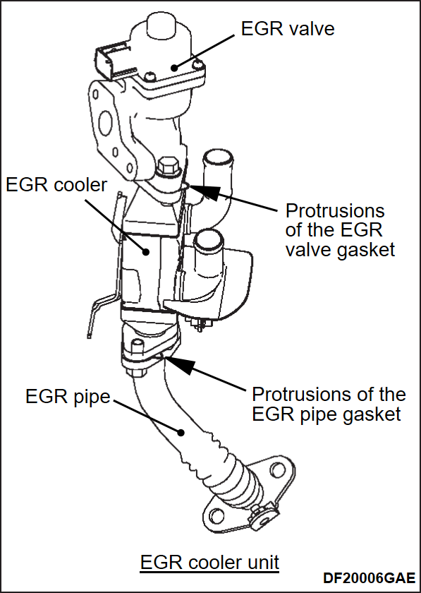
>>A<< EGR PIPE GASKET / EGR PIPE / EGR COOLER / EGR VALVE GASKET / EGR VALVE / EGR COOLER UNIT (EGR VALVE & EGR COOLER & EGR PIPE ASSEMBLY)/ EGR VALVE BRACKET INSTALLATION
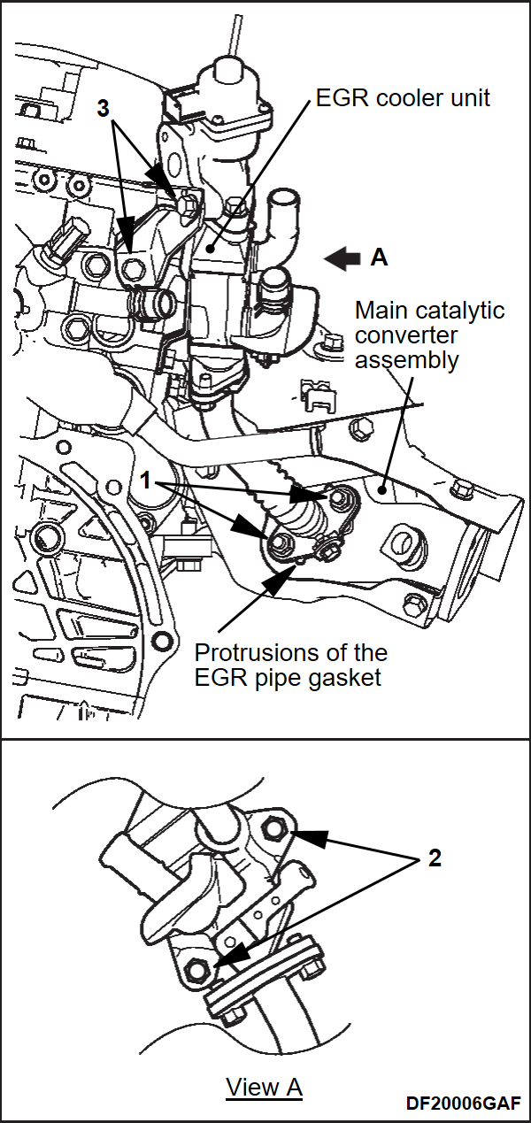
1. When assembling the EGR cooler unit, make sure all of the protrusion parts of each gasket are at the positions shown in the drawing.
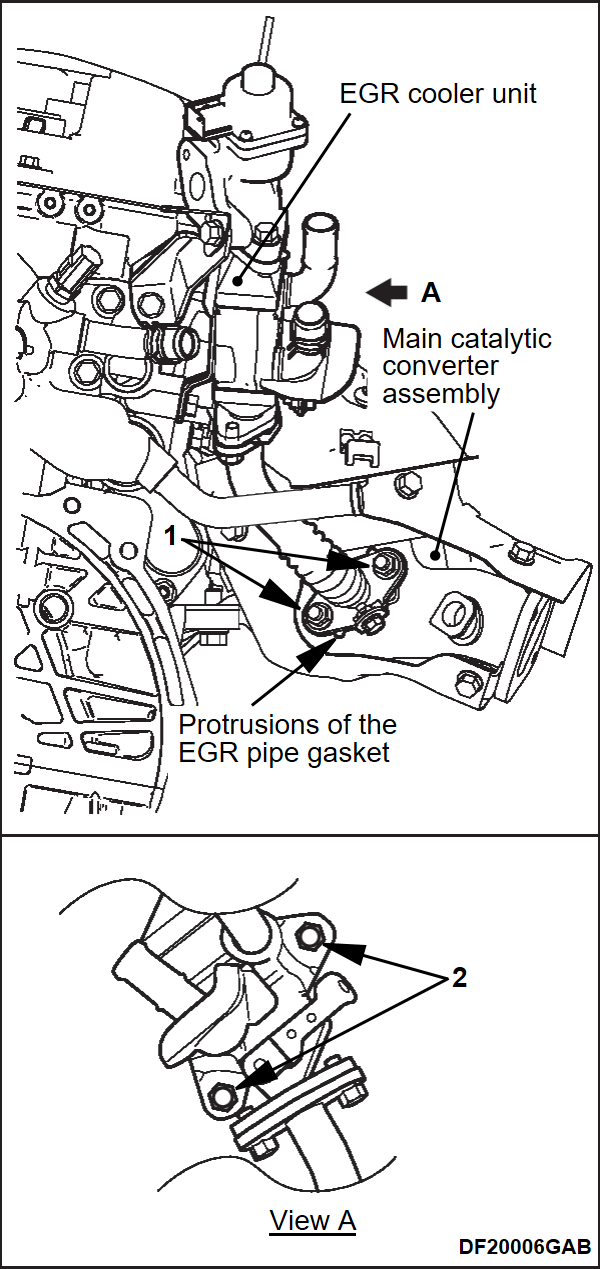
2. Assemble the EGR cooler unit and EGR pipe gasket (main catalytic converter assembly side) to the main catalytic converter assembly with the gasket protrusion parts in the positions shown in the drawing and temporarily tighten the nuts (1) and bolts (2) shown in drawings.
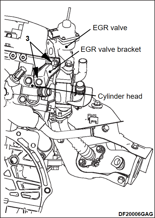
3. Assemble the EGR valve bracket to the EGR valve and cylinder head and temporarily tighten the bolts (3) shown in drawing.
4. Tighten the nuts (1) and bolts (2 and 3) in drawing of the previous steps to their specified torque.
Tightening torque:
- Nut in Figure 1: 25 ± 3 N·m (19 ± 1 ft-lb)
- Bolt in Figure 2: 24 ± 3 N·m (18 ± 1 ft-lb)
- Bolt in Figure 3: 22 ± 4 N·m (17 ± 2 ft-lb)
![[Previous]](../../../buttons/fprev.png)
![[Next]](../../../buttons/fnext.png)
