REMOVAL AND INSTALLATION
| caution |
|
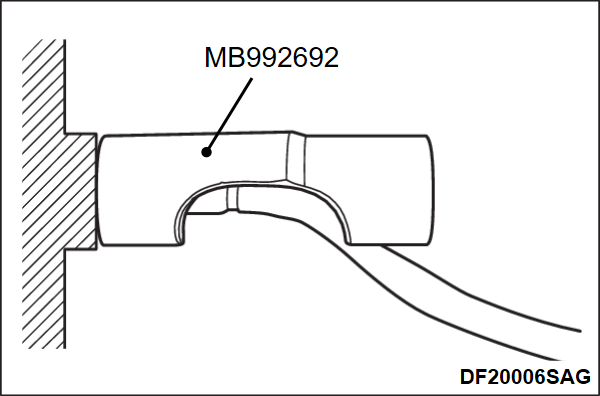
REMOVAL SERVICE POINT
INSTALLATION SERVICE POINTS
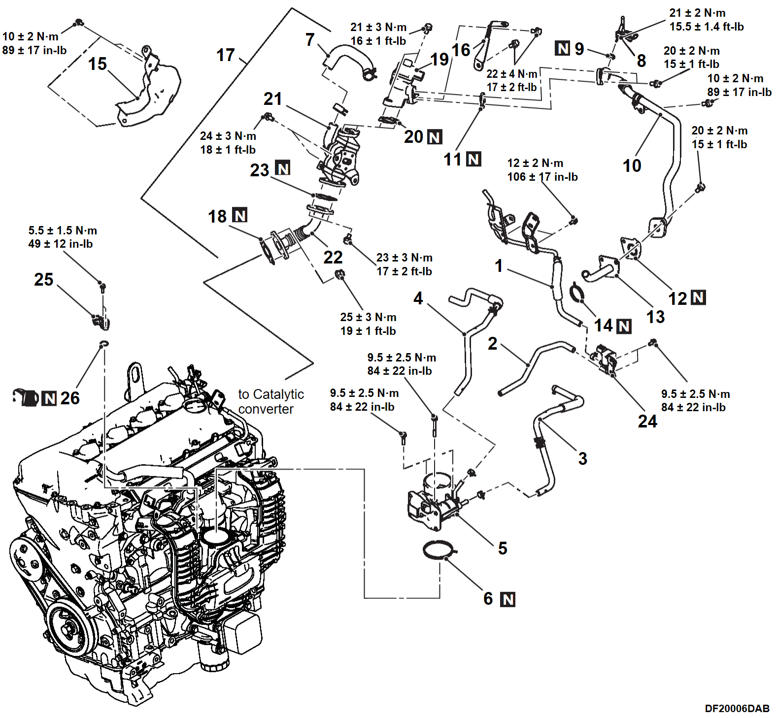
>>A<< O-RING/MANIFOLD ABSOLUTE PRESSURE SENSOR/PURGE CONTROL SOLENOID VALVE INSTALLATION
1. Apply a small amount of new engine oil to the manifold absolute pressure sensor O-ring.
| caution | Do not over-tighten. If the mounting screw is over-tightened, the inlet manifold can be damaged. |
2. Install the manifold absolute pressure sensor and the evaporative emission purge solenoid to the inlet manifold with care not to damage the O-ring.
3. Tighten the manifold absolute pressure sensor to the specified torque.
Tightening torque: 5.5 ± 1.5 N·m (49 ± 17 in-lb)
4. Tighten the evaporative emission purge solenoid to the specified torque.
Tightening torque: 10 ± 2 N·m (89 ± 17 in-lb)
>>B<< EGR PIPE GASKET/EGR PIPE/EGR COOLER/VALVE GASKET/EGR VALVE/EGR VALVE BRAKET INSTALLATION
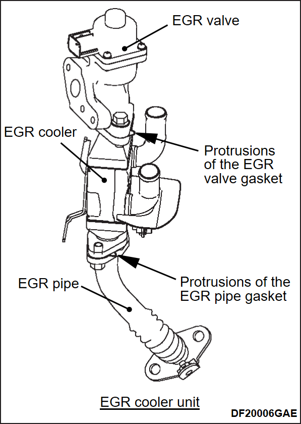
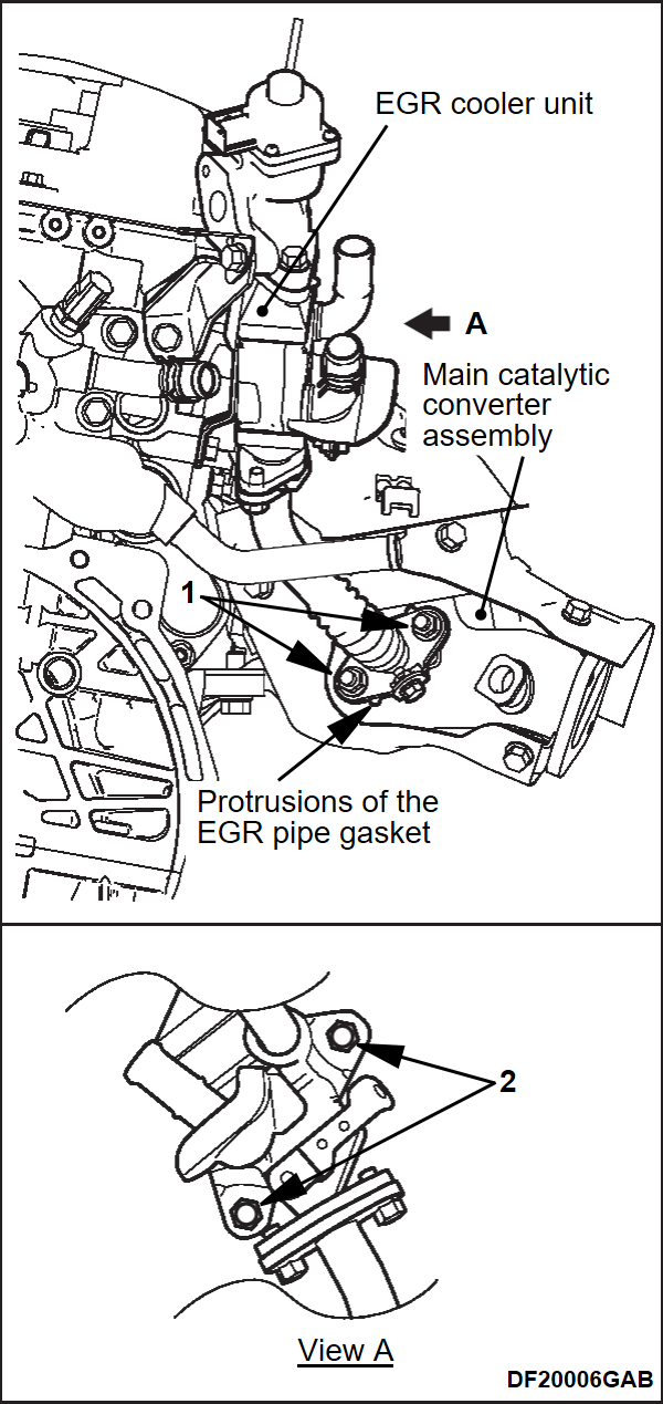
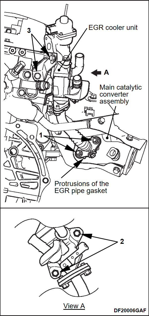
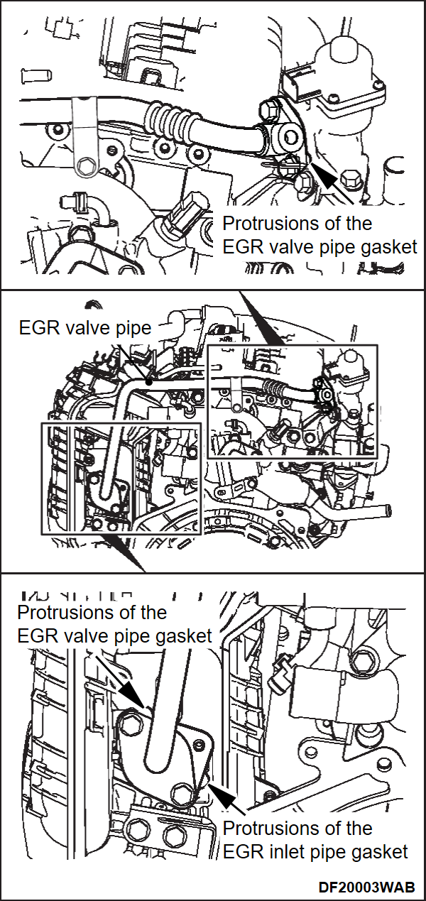
1. When assembling the EGR cooler, make sure all of the protrusion parts of each gasket are at the positions shown in the drawing.
2. Assemble the EGR cooler unit and EGR pipe gasket (main catalytic converter assembly side) to the main catalytic converter assembly with the gasket protrusion parts in the positions shown in the drawing and temporarily tighten the nuts (1) and bolts (2) shown in drawings.
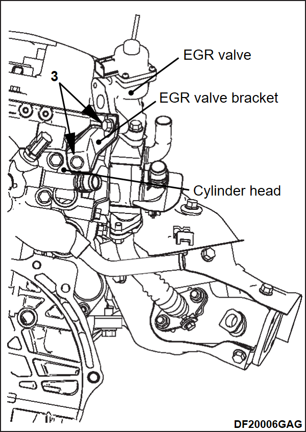
3. Assemble the EGR valve bracket to the EGR valve and cylinder head and temporarily tighten the bolts (3) shown in drawing.
4. Tighten the nuts (1) and bolts (2 and 3) in drawings of the previous steps to their specified torque.
Tightening torque:
- Nut in Figure 1: 25 ± 3 N·m (19 ± 1 ft-lb)
- Nut in Figure 2: 24 ± 3 N·m (18 ± 1 ft-lb)
- Nut in Figure 3: 22 ± 4 N·m (17 ± 2 ft-lb)
>>C<< EGR INLET PIPE/EGR VALVE GASKET/EGR VALVE PIPE INSTALLATION
1. Temporarily tighten each part so that the protrusions of each gasket and the EGR inlet pipe are positioned as shown in the figure.
2. Tighten each part to the specified torque.
Tightening torque: 20 ± 2 N·m (15 ± 1 ft-lb)
![[Previous]](../../../buttons/fprev.png)
![[Next]](../../../buttons/fnext.png)
