DTC P0AA6: Leak Detection, P0AA9: Leak Sensor Detection Circuit Short
| caution | Before replacing the ECU, ensure that the communication circuit is normal. |
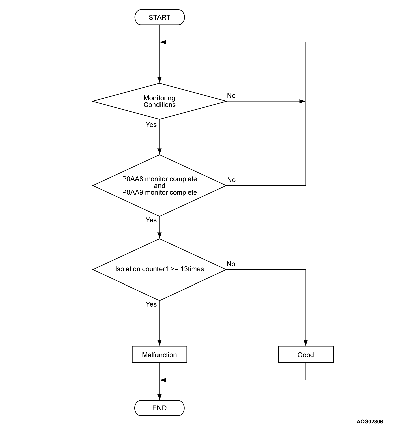
DESCRIPTIONS OF MONITOR METHODS <DTC P0AA6>
- The monitor detects a malfunction by using "Isolation counter 1" and "Isolation counter 2".
- The monitor executes after the diagnosis of the pre-check circuit (DTC P0AA8 and P0AA9) is completed.
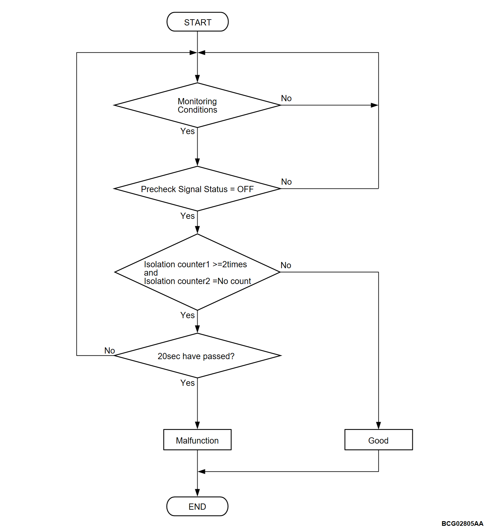
DESCRIPTIONS OF MONITOR METHODS <DTC P0AA9>
- The monitor executes immediately after the diagnosis of the isolation detect circuit (DTC P0AA8) is completed.
- Precheck circuit can simulate isolation state intentionally when "Precheck signal status is on".
- The monitor judges circuit malfunction when the monitor can detect the isolation state at "Precheck signal status is off".
- The monitor detects a malfunction by using "Isolation counter 1" and "Isolation counter 2".
MONITOR EXECUTION <DTC P0AA6>
- Continuous
MONITOR EXECUTION <DTC P0AA9>
- Once per driving cycle
MONITOR EXECUTION CONDITIONS (Other monitor and Sensor)
Other Monitor (There is no temporary DTC stored in memory for the item monitored below)
- EV-CAN monitor <DTC P0AA6>
- Not applicable <DTC P0AA9>
Sensor (The sensor below is determined to be normal)
- Not applicable
DTC SET CONDITIONS
Check Conditions
- BMU(SUB) power supply voltage is 8 volts to 16 volts.
- DTC P0AA8 and P0AA9 is not set.
Judgment Criterion
- Isolation counter 1 is more than 13 times.
Check Conditions
- BMU(SUB) power supply voltage is 8 volts to 16 volts.
- Time after above conditions satisfy is more than 3.5 seconds.
- Precheck signal status is off.
Judgment Criterion
- Isolation counter 1 is more than 2 times for 20 seconds.
- Isolation counter 2 is no counter.
FAIL-SAFE AND BACKUP FUNCTION <DTC P0AA6>
- Estimating computing for the current capacity of the battery is not performed.
- Automatic capacity measurement by the tester and smoothing of cell voltage are prohibited.
FAIL-SAFE AND BACKUP FUNCTION <DTC P0AA9>
- Not available
PROBABLE CAUSES
- Decrease of insulation resistance of high voltage system components
- The sub-battery management unit [BMU (SUB)] is failed.
- Malfunction of BMU (SUB) (malfunction of the leakage sensor function inside the ECU)
DIAGNOSIS
Required Special Tools
- MB991223: Wiring harness set
- MB992006: Extra fine probe
- MB992355: Electric insulation tester
| danger | When high voltage system components are serviced, be sure to pull service plugs to shut down high voltage (Refer to  ). ). |
| danger | When pulling service plugs, wear the specified protective equipment (Refer to  ). ). |
STEP 1. Using scan tool (M.U.T.-IIISE), check whether the other DTC is set.
Is the DTC related to PHEV-ECU system set?
STEP 2. Using scan tool (M.U.T.-IIISE), check whether the other DTC is set.
Is the DTC related to A/C compressor or electric heater-ECU system set?
STEP 3. Using scan tool (M.U.T.-IIISE), read the DTC.
- Wait 20 seconds after operate the electric motor switch without depressing the brake pedal and turn ON the power supply mode of electric motor switch.
- Selector lever position indicator: P
| note | If the diagnostic trouble code is set with the power supply mode of electric motor switch turned ON, an electric leak could occur inside the main drive lithium-ion battery. |
Is the DTC set?
STEP 4. Measure the voltage at the service plug connector. <High voltage>
| danger | When high voltage system components are serviced, be sure to pull service plugs to shut down high voltage before serving (Refer to  ). ). |
| danger | When pulling service plugs, wear the specified protective equipment (Refer to  ). ). |
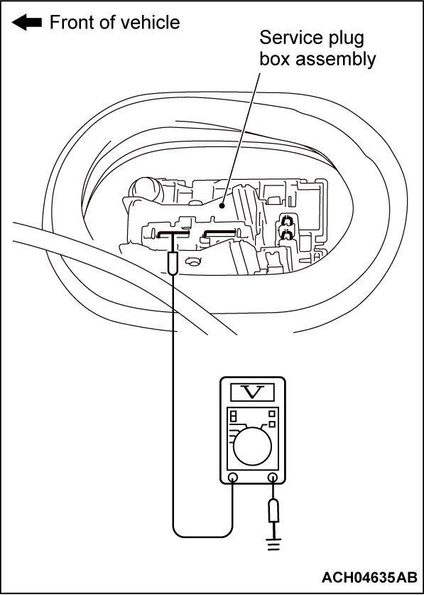
(1) Disconnect service plug, and measure at service plug box assembly side.
(2) Connect a high-voltage compatible multimeter between service plug box assembly CMU ID 07 side terminal and body ground.
OK: Approximately 0 V
Is the check result normal?
STEP 5. Check contactor itself.
- Check main contactor (P) and charging contactor itself.
| note | When a DTC is set with the electric motor switch ON, there may be electric leakage inside the main drive lithium-ion battery. |
Is the check result normal?
 Disconnect the connectors between CMU ID07 and ID11 one by one, and check each connector for voltage. Then check the wires from the service plug through main contactor (P) to the charging contactor and the bus bar for short circuit, and repair if necessary. Make sure that the bus bar is connected securely (Refer to
  ). Then assemble the main drive lithium-ion battery according to the specified procedure (Refer to
  ). Then go to Step 41
 .
.STEP 6. Measure the voltage at the service plug connector. <High voltage>
| danger | When high voltage system components are serviced, be sure to pull service plugs to shut down high voltage before serving (Refer to  ). ). |
| danger | When pulling service plugs, wear the specified protective equipment (Refer to  ). ). |
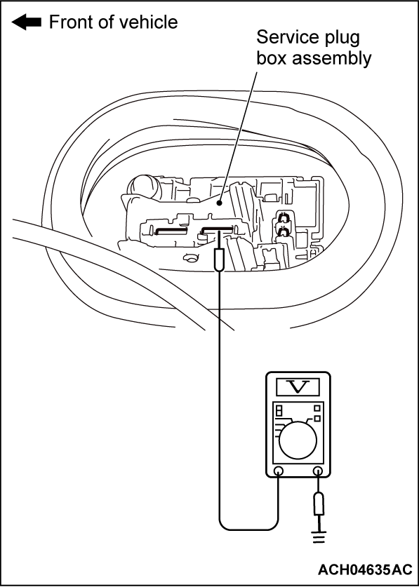
(1) Disconnect service plug, and measure at service plug box assembly side.
(2) Connect a high-voltage compatible multimeter between service plug box assembly CMU ID 05 side terminal and body ground.
OK: Approximately 0 V
Is the check result normal?
STEP 7. Check contactor itself.
- Check main contactor (N) itself.
Is the check result normal?
 Disconnect the connectors between CMU ID01 and ID05 one by one, and check each connector for voltage. Then check the wires from the service plug to main contactor (N) and the bus bar for short circuit, and repair if necessary, or check the cable from the sub BMU to bus bar for short circuit, and repair if necessary (Refer to
  ). Then assemble the main drive lithium-ion battery according to the specified procedure. (Refer to
  ). Then go to Step 41
 .
.STEP 8. Using scan tool (M.U.T.-IIISE), check whether the DTC is set.
- Wait 20 seconds after operate the electric motor switch with depressing the brake pedal and turn ON the power supply mode of electric motor switch.
- Ready indicator is illuminated
- Selector lever position indicator: P
- A/C switch: OFF
Is the DTC set?
STEP 9. Measure the voltage at the power drive unit connector. <High voltage>
| danger | When high voltage system components are serviced, be sure to pull service plugs to shut down high voltage before serving (Refer to  ). ). |
| danger | When pulling service plugs, wear the specified protective equipment (Refer to  ). ). |
| caution | When the insulation resistance is measured, set the range of the special tool electric insulation tester (MB992355) to 500 Volts. When the insulation resistance is measured at the range more than 500 Volts, the component may be damaged. |
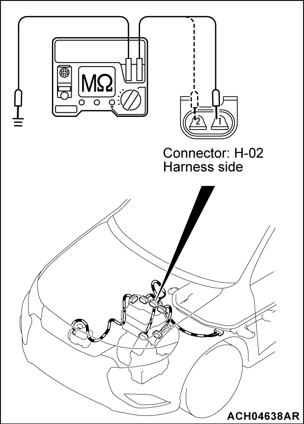
(1) Disconnect the H-02 power drive unit connector, and measure at the wiring harness side.
(2) Use the special tool electric insulation tester (MB992355) to set the range to 500 Volts.
(3) Check the insulation resistance between H-02 power drive unit connector (terminal No.1) and body ground. (P terminal)
OK: 10 MΩ or more
(4) Check the insulation resistance between H-02 power drive unit connector (terminal No.2) and body ground. (N terminal)
OK: 10 MΩ or more
Is the check result normal?
STEP 10. Measure the voltage at the power drive unit connector. <High voltage>
| caution | When the insulation resistance is measured, set the range of the special tool electric insulation tester (MB992355) to 500 Volts. When the insulation resistance is measured at the range more than 500 Volts, the component may be damaged. |
(1) Disconnect the H-02 power drive unit connector and H-10 main drive lithium-ion battery connector, and measure at the wiring harness side.
(2) Use the special tool electric insulation tester (MB992355) to set the range to 500 Volts.
(3) Check the insulation resistance between H-02 power drive unit connector (terminal No.1) and body ground. (P terminal)
OK: 10 MΩ or more
(4) Check the insulation resistance between H-02 power drive unit connector (terminal No.2) and body ground. (N terminal)
OK: 10 MΩ or more
Is the check result normal?
 Remove the battery tray cover (Refer to
  ). Check and modify the harness and the bus bar between the main drive lithium-ion battery connector and the main contactor (P), also between the main drive lithium-ion battery connector and the main connector (N) (Refer to
  ). Then, assemble the main drive lithium-ion battery assembly (Refer to
  ). Then go to Step 41
 .
.STEP 11. Measure the voltage at the power drive unit connector. <High voltage>
| caution | When the insulation resistance is measured, set the range of the special tool electric insulation tester (MB992355) to 500 Volts. When the insulation resistance is measured at the range more than 500 Volts, the component may be damaged. |
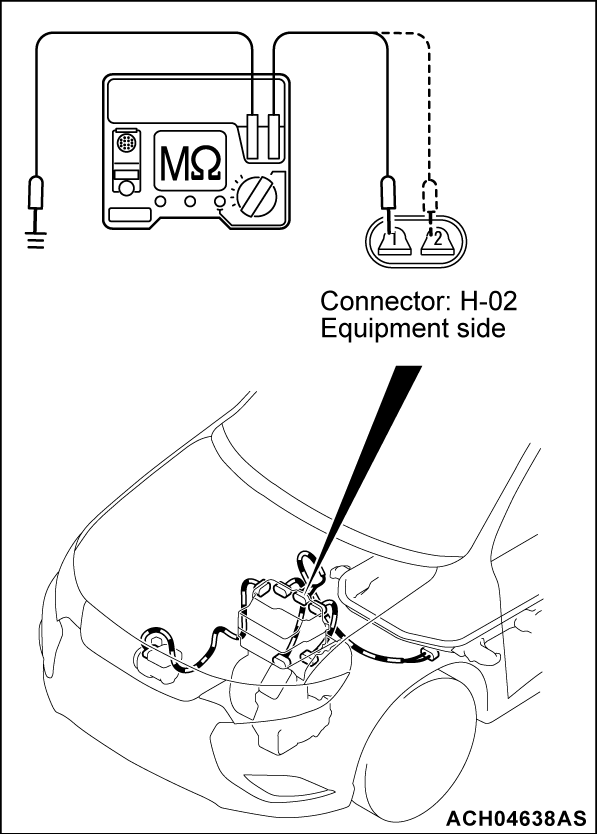
(1) Disconnect the H-02 power drive unit connector, and measure at the equipment side.
(2) Use the special tool electric insulation tester (MB992355) to set the range to 500 Volts.
(3) Check the insulation resistance between H-02 power drive unit connector (terminal No.1) and body ground. (P terminal)
OK: 10 MΩ or more
(4) Check the insulation resistance between H-02 power drive unit connector (terminal No.2) and body ground. (N terminal)
OK: 10 MΩ or more
Is the check result normal?
STEP 12. Measure the voltage at the power drive unit connector. <High voltage>
| caution | When the insulation resistance is measured, set the range of the special tool electric insulation tester (MB992355) to 500 Volts. When the insulation resistance is measured at the range more than 500 Volts, the component may be damaged. |
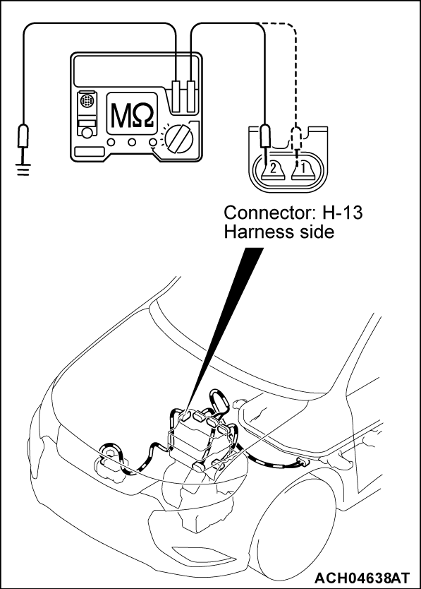
(1) Disconnect the H-13 power drive unit connector, and measure at the wiring harness side.
(2) Use the special tool electric insulation tester (MB992355) to set the range to 500 Volts.
(3) Check the insulation resistance between H-13 power drive unit (A/C compressor) connector (terminal No.2) and body ground. (P terminal)
OK: 10 MΩ or more
(4) Check the insulation resistance between H-13 power drive unit (A/C compressor) connector (terminal No.1) and body ground. (N terminal)
OK: 10 MΩ or more
Is the check result normal?
STEP 13. Measure the voltage at the power drive unit connector. <High voltage>
(1) Disconnect the H-13 power drive unit connector, and measure at the wiring harness side.
(2) Use the special tool electric insulation tester (MB992355) to set the range to 500 Volts.
(3) Check the insulation resistance between H-13 power drive unit (A/C compressor) connector (terminal No.2) and body ground. (P terminal)
OK: 10 MΩ or more
(4) Check the insulation resistance between H-13 power drive unit (A/C compressor) connector (terminal No.1) and body ground. (N terminal)
OK: 10 MΩ or more
Is the check result normal?
 Check end
STEP 14. Check the A/C compressor assembly for the insulation resistance.
Check the A/C compressor assembly for the insulation resistance (Refer to GROUP 55 - Compressor Assembly - Inspection  ).
).
 ).
).Is the check result normal?
STEP 15. Check the power drive unit for the insulation resistance.
Power drive unit for the insulation resistance check (Refer to GROUP 54Db - Power Drive Unit - Checking Insulation Resistance  ).
).
 ).
).Is the check result normal?
STEP 16. Measure the voltage at the rear electric motor control unit connector. <High voltage>
| danger | When high voltage system components are serviced, be sure to pull service plugs to shut down high voltage before serving (Refer to  ). ). |
| danger | When pulling service plugs, wear the specified protective equipment (Refer to  ). ). |
| caution | When the insulation resistance is measured, set the range of the special tool electric insulation tester (MB992355) to 500 Volts. When the insulation resistance is measured at the range more than 500 Volts, the component may be damaged. |
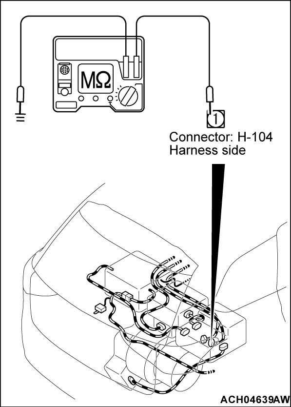
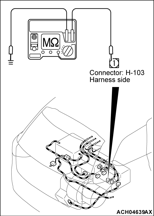
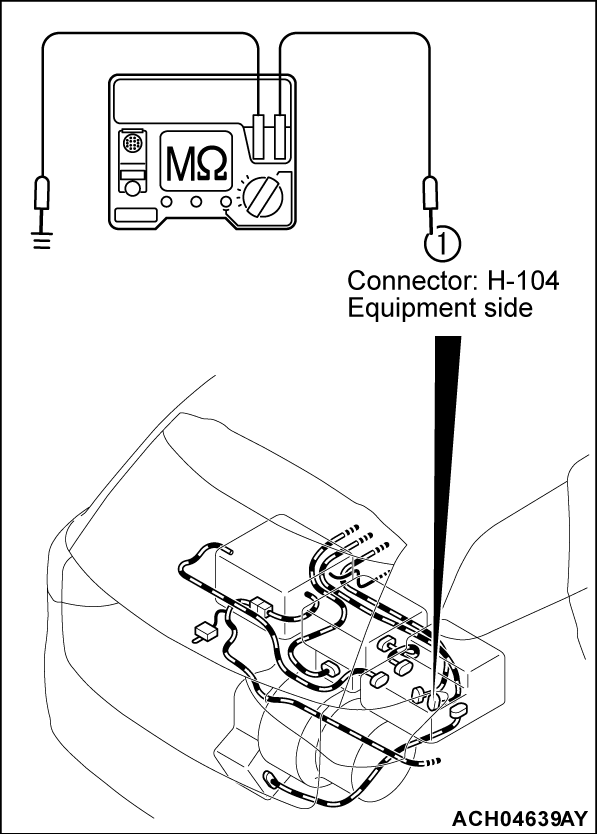
(1) Disconnect the H-103 and H-104 REMCU connector, and measure at the wiring harness side.
(2) Use the special tool electric insulation tester (MB992355) to set the range to 500 Volts.
(3) Check the insulation resistance between H-104 REMCU (terminal No.1) connector and body ground. (main drive lithium-ion battery P)
OK: 10 MΩ or more
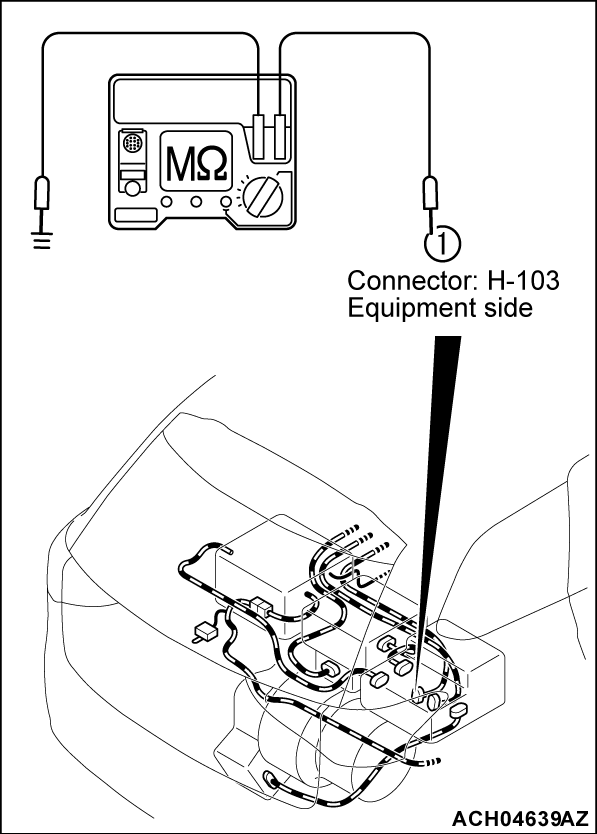
(4) Check the insulation resistance between H-103 REMCU (terminal No.1) connector and body ground. (main drive lithium-ion battery N)
OK: 10 MΩ or more
Is the check result normal?
STEP 17. Check REMCU (main drive lithium-ion battery P) and REMCU (main drive lithium-ion battery N) for the insulation resistance.
| caution | When the insulation resistance is measured, set the range of the special tool electric insulation tester (MB992355) to 500 Voltsolts. When the insulation resistance is measured at the range more than 500 Volts, the component may be damaged. |
(1) Disconnect the H-103 and H-104 REMCU connector, and measure at the wiring harness side.
(2) Disconnect connector, H-09 main drive lithium-ion battery (normal charging P) connector and H-08 main drive lithium-ion battery (normal charging N) connector.
(3) Use the special tool electric insulation tester (MB992355) to set the range to 500 Volts.
(4) Check the insulation resistance between H-104 REMCU (terminal No.1) connector and body ground. (main drive lithium-ion battery P)
OK: 10 MΩ or more
(5) Check the insulation resistance between H-103 REMCU (terminal No.1) connector and body ground. (main drive lithium-ion battery N)
OK: 10 MΩ or more
Is the check result normal?
 Remove the battery tray cover (Refer to
  ). Check and modify the harness and the bus bar between the main drive lithium-ion battery connector and the main contactor (P), also between the main drive lithium-ion battery connector and the main connector (N) (Refer to
  ). Then, assemble the main drive lithium-ion battery assembly (Refer to
  ). Then go to Step 41
 .
.STEP 18. Measure the voltage at the rear electric motor control unit connector. <High voltage>
| caution | When the insulation resistance is measured, set the range of the special tool electric insulation tester (MB992355) to 500 Volts. When the insulation resistance is measured at the range more than 500 Volts, the component may be damaged. |
(1) Disconnect the H-103 and H-104 REMCU connector, and measure at the equipment side.
(2) Use the special tool electric insulation tester (MB992355) to set the range to 500 Volts.
(3) Check the insulation resistance between H-104 REMCU (terminal No.1) connector and body ground. (main drive lithium-ion battery P)
OK: 10 MΩ or more
(4) Check the insulation resistance between H-103 REMCU (terminal No.1) connector and body ground. (main drive lithium-ion battery N)
OK: 10 MΩ or more
Is the check result normal?
STEP 19. Check the REMCU (On board charger/DC-DC converter) connector for the insulation resistance.
| caution | When the insulation resistance is measured, set the range of the special tool electric insulation tester (MB992355) to 500 Volts. When the insulation resistance is measured at the range more than 500 Volts, the component may be damaged. |
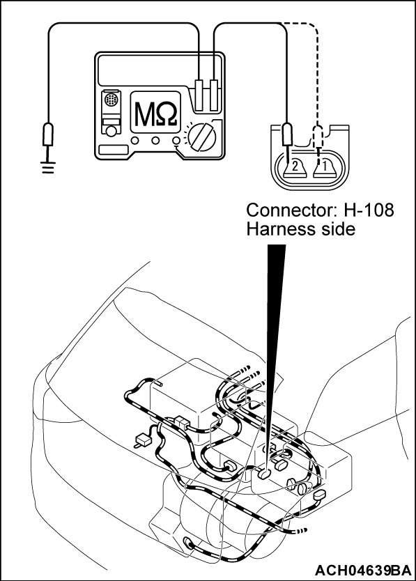
(1) Disconnect the H-108 REMCU connector, and measure at the wiring harness side.
(2) Use the special tool electric insulation tester (MB992355) to set the range to 500 Volts.
(3) Check the insulation resistance between H-108 REMCU (on board charger/DC-DC converter) connector (terminal No.2) and body ground. (P terminal)
OK: 10 MΩ or more
(4) Check the insulation resistance between H-108 REMCU (on board charger/DC-DC converter) connector (terminal No.1) and body ground. (N terminal)
OK: 10 MΩ or more
Is the check result normal?
STEP 20. Check the REMCU (electric heater) for the insulation resistance.
| caution | When the insulation resistance is measured, set the range of the special tool electric insulation tester (MB992355) to 500 Volts. When the insulation resistance is measured at the range more than 500 Volts, the component may be damaged. |
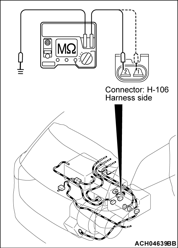
(1) Disconnect the H-106 REMCU connector, and measure at the wiring harness side.
(2) Use the special tool electric insulation tester (MB992355) to set the range to 500 Volts.
(3) Check the insulation resistance between H-106 REMCU (electric heater) connector (terminal No.2) and body ground. (P terminal)
OK: 10 MΩ or more
(4) Check the insulation resistance between H-106 REMCU (electric heater) connector (terminal No.1) and body ground. (N terminal)
OK: 10 MΩ or more
Is the check result normal?
STEP 21. Check the electric heater for the insulation resistance.
Check the electric heater for the insulation resistance (Refer to GROUP 55 - Heater Water Pump - Inspection  ).
).
 ).
).Is the check result normal?
STEP 22. Check the REMCU for the insulation resistance.
Check the REMCU for the insulation resistance (Refer to GROUP 54Db - REMCU - Checking Insulation Resistance  ).
).
 ).
).Is the check result normal?
STEP 23. Using scan tool (M.U.T.-IIISE), check whether the DTC is set.
(1) Ready indicator is illuminated
(2) Selector lever position indicator: D
(3) Loosen the depression of the brake pedal with the parking brake activated.
Is the DTC set?
STEP 24. Measure the voltage at the power drive unit connector. <High voltage>
| danger | When high voltage system components are serviced, be sure to pull service plugs to shut down high voltage before serving (Refer to  ). ). |
| danger | When pulling service plugs, wear the specified protective equipment (Refer to  ). ). |
| caution | When the insulation resistance is measured, set the range of the special tool electric insulation tester (MB992355) to 500 Volts. When the insulation resistance is measured at the range more than 500 Volts, the component may be damaged. |
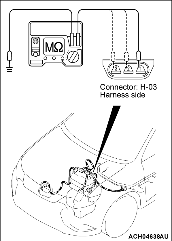
(1) Disconnect the H-03 power drive unit connector, and measure at the wiring harness side.
(2) Use the special tool electric insulation tester (MB992355) to set the range to 500 Volts.
(3) Check the insulation resistance between H-03 power drive unit (front motor) connector (terminal No.1) and body ground. (MU terminal)
OK: 10 MΩ or more
(4) Check the insulation resistance between H-03 power drive unit (front motor) connector (terminal No.2) and body ground. (MV terminal)
OK: 10 MΩ or more
(5) Check the insulation resistance between H-03 power drive unit (front motor) connector (terminal No.3) and body ground. (MW terminal)
OK: 10 MΩ or more
Is the check result normal?
STEP 25. Check the front motor (power unit) for the insulation resistance.
Check the front motor assembly for the insulation resistance (Refer to GROUP 54Db - Front Motor - Checking Insulation Resistance  ).
).
 ).
).Is the check result normal?
STEP 26. Check the oil filter of the EV cooling system.
Check that the oil filter of the EV cooling system is not contaminated with foreign material and is not broken (Refer to GROUP 14B - On-vehicle Service <Oil Cooling System>, Oil Change  ).
).
 ).
).Is the check result normal?
STEP 27. Check the power drive unit connector for the insulation resistance.
| danger | When high voltage system components are serviced, be sure to pull service plugs to shut down high voltage before serving (Refer to  ). ). |
| danger | When pulling service plugs, wear the specified protective equipment (Refer to  ). ). |
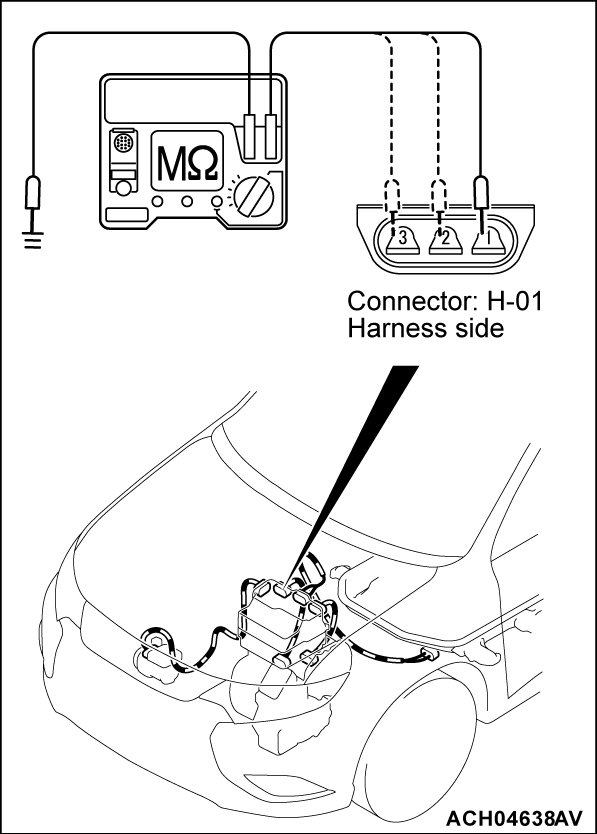
(1) Disconnect the H-01 power drive unit connector, and measure at the wiring harness side.
(2) Use the special tool electric insulation tester (MB992355) to set the range to 500 Volts.
(3) Check the insulation resistance between H-01 power drive unit (generator) connector (terminal No.1) and body ground. (GU terminal)
OK: 10 MΩ or more
(4) Check the insulation resistance between H-01 power drive unit (generator) connector (terminal No.2) and body ground. (GV terminal)
OK: 10 MΩ or more
(5) Check the insulation resistance between H-01 power drive unit (generator) connector (terminal No.3) and body ground. (GW terminal)
OK: 10 MΩ or more
Is the check result normal?
STEP 28. Check the generator (power unit) for the insulation resistance.
Check the generator for the insulation resistance (Refer to GROUP 54Db - Generator - Checking Insulation Resistance  ).
).
 ).
).Is the check result normal?
STEP 29. Check the power drive unit for the insulation resistance.
Check the power drive unit for the insulation resistance (Refer to GROUP 54Db - Power Drive Unit - Checking Insulation Resistance  ).
).
 ).
).Is the check result normal?
STEP 30. Check the REMCU for the insulation resistance.
| danger | When high voltage system components are serviced, be sure to pull service plugs to shut down high voltage before serving (Refer to  ). ). |
| danger | When pulling service plugs, wear the specified protective equipment (Refer to  ). ). |
| caution | When the insulation resistance is measured, set the range of the special tool electric insulation tester (MB992355) to 500 Volts. When the insulation resistance is measured at the range more than 500 Volts, the component may be damaged. |
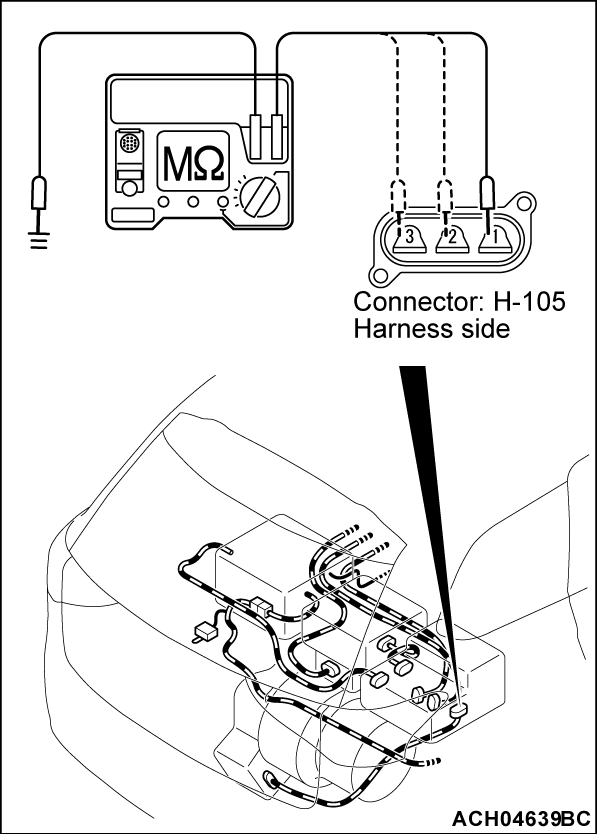
(1) Disconnect the H-105 REMCU connector, and measure at the wiring harness side.
(2) Use the special tool electric insulation tester (MB992355) to set the range to 500 Volts.
(3) Check the insulation resistance between H105 REMCU (rear motor) connector (terminal No.1) and body ground. (U terminal)
OK: 10 MΩ or more
(4) Check the insulation resistance between H-105 REMCU (rear motor) connector (terminal No.2) and body ground. (V terminal)
OK: 10 MΩ or more
(5) Check the insulation resistance between H-105 REMCU (rear motor) connector (terminal No.3) and body ground. (W terminal)
OK: 10 MΩ or more
Is the check result normal?
STEP 31. Check the rear motor for the insulation resistance.
Check the rear motor assembly for the insulation resistance (Refer to GROUP 54Db - Rear Motor - Checking Insulation Resistance  ).
). Replace the harness between REMCU (rear motor) connector and rear motor (power unit) connector.
 ).
).Is the check result normal?
 Replace the harness between REMCU (rear motor) connector and rear motor (power unit) connector.
STEP 32. Check the REMCU for the insulation resistance
Is the check result normal?
STEP 33. Using scan tool (M.U.T.-IIISE), check whether the DTC is set.
- Wait 20 seconds after operate the electric motor switch without depressing the brake pedal and turn ON the power supply mode of electric motor switch.
- A/C switch: ON (A/C compressor: ON)
Is the DTC set?
STEP 34. Using scan tool (M.U.T.-IIISE), read the DTC.
(1) After replacing the A/C refrigerant and the compressor oil.
(2) Erase the set DTC.
(3) Operate the electric motor switch without depressing the brake pedal and turn ON the power supply mode of electric motor switch.
(4) Selector lever position indicator: P
(5) A/C switch: ON (A/C compressor: ON)
(6) Confirm whether the DTC is set.
Is the DTC set?
STEP 35. Using scan tool (M.U.T.-IIISE), check the special function.
Is the DTC set?
STEP 36. Using scan tool (M.U.T.-IIISE), check whether the DTC is set.
(1) During the normal charging
(2) Confirm whether the DTC is set.
Is the DTC set?
STEP 37. Check the charging cable.
Check that the POWER indicator is lit, also the CHARGING indicator and the FAULT indicator are momentarily lit.
Is the check result normal?
STEP 38. Using scan tool (M.U.T.-IIISE), check whether the DTC is set.
(1) Select "BMU" from System select Screen of the scan tool (M.U.T.-IIISE).
(2) Select the "Special Function" from the main BMU screen.
(3) Select the "Test" from the Special Function screen
(4) Select the "Battery heating system drive" from the Test screen.
(5) Confirm whether the DTC is set.
Is the DTC set?
STEP 39. Check contactor itself.
Is the check result normal?
 Check the bus bar from the PTC heater contactor (P) through main contactor (P) to the charging contactor for short circuit, and repair if necessary. Make sure that the bus bar is connected securely (Refer to
  ). Then assemble the main drive lithium-ion battery according to the specified procedure (Refer to
  ). Then go to Step 40
 .
.STEP 40. Check contactor itself.
Is the check result normal?
![[Previous]](../../../buttons/fprev.png)
![[Next]](../../../buttons/fnext.png)
