[Previous][Next]
DIAGNOSTIC FUNCTION
 
 
WHEN BATTERY MANAGEMENT UNIT (BMU) OR SUB BATTERY MANAGEMENT UNIT [BMU (SUB)] ABNORMALITY IS DETECTED
When the BMU or BMU (SUB) detects the abnormality, the diagnostic trouble code should be set. The PHEV-ECU monitors to check whether the BMU or BMU (SUB) has abnormalities.


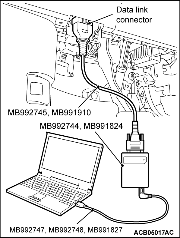
HOW TO CONNECT THE SCAN TOOL (M.U.T.-IIISE)
Required Special Tools:
  • MB992744: Vehicle communication interface-Lite (V.C.I.-Lite)
  • MB992745: V.C.I.-Lite main harness A
  • MB992747: V.C.I.-Lite USB cable short
  • MB992748: V.C.I.-Lite USB cable long
  • MB991958: Scan Tool (M.U.T.-III Sub Assembly)
    • MB991824: Vehicles Communication Interface (V.C.I.)
    • MB991827: M.U.T.-III USB Cable
    • MB991910: M.U.T.-III Main Harness A (Vehicles with CAN communication system)
cautionTo prevent damage to scan tool (M.U.T.-IIISE), always turn off the power supply mode of the electric motor switch before connecting or disconnecting scan tool (M.U.T.-IIISE).
1. Ensure that the power supply mode of the electric motor switch should be turned off.
2. Start up the personal computer.
3. Connect special tool MB992747/M992748 or special tool MB991827 to special tool MB992744 or special tool MB991824 and the personal computer.
4. Connect special tool MB992745 or special tool MB991910 to special tool MB992744 or special tool MB991824.
5. Connect special tool MB992745 or special tool MB991910 to the data link connector.
noteWhen the special tool MB992745 is connected to the data link connector, the special tool MB992744 indicator light will be illuminated in a green color.
6. Turn the power switch of special tool MB991824 to the "ON" position. <When using the special tool MB991824>
noteWhen special tool MB991824 is energized, special tool MB991824 indicator light will be illuminated in a green color.
7. Start the M.U.T.-III system on the personal computer.
noteDisconnecting scan tool (M.U.T.-IIISE) is the reverse of the connecting sequence, making sure that the power supply mode of the electric motor switch should be turned off.


HOW TO READ AND ERASE DIAGNOSTIC TROUBLE CODES
Required Special Tools:
  • MB992744: Vehicle communication interface-Lite (V.C.I.-Lite)
  • MB992745: V.C.I.-Lite main harness A
  • MB992747: V.C.I.-Lite USB cable short
  • MB992748: V.C.I.-Lite USB cable long
  • MB991958: Scan Tool (M.U.T.-III Sub Assembly)
    • MB991824: Vehicles Communication Interface (V.C.I.)
    • MB991827: M.U.T.-III USB Cable
    • MB991910: M.U.T.-III Main Harness A (Vehicles with CAN communication system)
noteIf the 12V Starter Battery voltage is low, diagnostic trouble codes will not be set. Check the battery if scan tool (M.U.T.-IIISE) does not display.
1. Connect scan tool (M.U.T.-IIISE) to the data link connector.
2. Turn on the power supply mode of the electric motor switch.
3. Select "STV".
4. Select "BMU" or "BMU(SUB)".
5. Select "Diagnostic Trouble Code" to read the DTC.
6. If a DTC is set, it is shown.
7. Select "Erase DTCs" to erase the DTC.


HOW TO READ DATA LIST
Required Special Tools:
  • MB992744: Vehicle communication interface-Lite (V.C.I.-Lite)
  • MB992745: V.C.I.-Lite main harness A
  • MB992747: V.C.I.-Lite USB cable short
  • MB992748: V.C.I.-Lite USB cable long
  • MB991958: Scan Tool (M.U.T.-III Sub Assembly)
    • MB991824: Vehicles Communication Interface (V.C.I.)
    • MB991827: M.U.T.-III USB Cable
    • MB991910: M.U.T.-III Main Harness A (Vehicles with CAN communication system)
1. Connect the scan tool (M.U.T.-IIISE) to the data link connector.
2. Turn on the power supply mode of the electric motor switch.
3. Select "STV".
4. Select "BMU" or "BMU(SUB)".
5. Select "Data List".
6. Select an appropriate item and select the "OK" button.


HOW TO PERFORM ACTUATOR TEST
Required Special Tools:
  • MB992744: Vehicle communication interface-Lite (V.C.I.-Lite)
  • MB992745: V.C.I.-Lite main harness A
  • MB992747: V.C.I.-Lite USB cable short
  • MB992748: V.C.I.-Lite USB cable long
  • MB991958: Scan Tool (M.U.T.-III Sub Assembly)
    • MB991824: Vehicles Communication Interface (V.C.I.)
    • MB991827: M.U.T.-III USB Cable
    • MB991910: M.U.T.-III Main Harness A (Vehicles with CAN communication system)
1. Connect the scan tool (M.U.T.-IIISE) to the data link connector.
2. Turn on the power supply mode of the electric motor switch.
3. Select "STV".
4. Select "BMU" or "BMU(SUB)".
5. Select "Actuator Test".
6. Select an appropriate item and select the "OK" button.


NUMBERING CMU ID PROCEDURE
Because having basically been completed at the factory, numbering the CMU ID of the main drive lithium-ion battery is not necessary. However, if the CMU or the battery module is replaced due to the check or the maintenance inside the main drive lithium-ion battery, number the CMU ID after the check or the maintenance.
 
 
WORK PROCEDURE
noteDo not number the CMU ID while the main drive lithium-ion battery is being charged.
Required Special Tools:
  • MB992744: Vehicle communication interface-Lite (V.C.I.-Lite)
  • MB992745: V.C.I.-Lite main harness A
  • MB992747: V.C.I.-Lite USB cable short
  • MB992748: V.C.I.-Lite USB cable long
  • MB991958: Scan Tool (M.U.T.-III Sub Assembly)
    • MB991824: Vehicles Communication Interface (V.C.I.)
    • MB991827: M.U.T.-III USB Cable
    • MB991910: M.U.T.-III Main Harness A (Vehicles with CAN communication system)
1. Connect scan tool (M.U.T.-IIISE) to the data link connector.
2. Operate the electric motor switch without the brake pedal is depressed and turn ON the power supply mode of electric motor switch.
3. Select "STV".
4. Select "BMU".
5. Select "Special Function".
6. Select "CMU ID numbering".
7. Press the OK button and number the CMU ID. The data list item No. 1 Execution status should show [Numbering] while the CMU ID is being numbered.
8. After numbering the CMU ID, check that the data of the list are changed as shown below. If numbering the CMU ID is not correct, number the CMU ID again.
 
Item No.Inspection itemNormal value judgment
1Execution statusComplete
2Data 1(ID info.1)Complete
3Data 1(ID info.2)Complete
4Data 1(ID info.3)Complete
5Data 1(ID info.4)Complete
6Data 2(ID info.1)Complete
7Data 2(ID info.2)Complete
8Data 2(ID info.3)Complete
9Data 2(ID info.4)Complete
10Data 3(ID info.1)Complete
11Data 3(ID info.2)Complete
12Data 3(ID info.3)-*1
13Data 3(ID info.4)-*1
note*1: The inspection item is displayed on the scan tool (M.U.T.-IIISE). However, this check is not necessary.


PRE-CHECK PROCEDURE OF MAIN DRIVE LITHIUM-ION BATTERY GROUND LEAKAGE SENSOR
Use the scan tool (M.U.T.-IIISE) to perform the pre-check of the main drive lithium-ion battery ground leakage sensor. This allows the main drive lithium-ion battery ground leakage sensor to easily be checked.
noteIf "DTC P0AA6: Leak Detection" is set in the BMU (SUB) as a current trouble, the pre-check cannot be performed as no pre-check signal is transmitted.
 
 
CONFIRMATION METHOD
1.
Required Special Tools:
  • MB992744: Vehicle communication interface-Lite (V.C.I.-Lite)
  • MB992745: V.C.I.-Lite main harness A
  • MB992747: V.C.I.-Lite USB cable short
  • MB992748: V.C.I.-Lite USB cable long
  • MB991958: Scan Tool (M.U.T.-III Sub Assembly)
    • MB991824: Vehicles Communication Interface (V.C.I.)
    • MB991827: M.U.T.-III USB Cable
    • MB991910: M.U.T.-III Main Harness A (Vehicles with CAN communication system)
Connect scan tool (M.U.T.-IIISE) to the data link connector.
2. Turn on the power supply mode of the electric motor switch.
3. Select "STV".
4. Select "BMU(SUB)".
5. Select "Special Function".
6. Select "TEST".
7. Select "Leak sensor precheck".
8. Press the OK button to perform the pre-check of the main drive lithium-ion battery ground leakage sensor. Check the "Leak sensor output(Precheck)" displayed on the scan tool (M.U.T.-IIISE) and check that the "ON" .
9. If "OFF" is displayed, perform the troubleshooting.


CHECK ON FREEZE FRAME DATA
When judging malfunctions and storing diagnostic trouble codes, the main BMU or BMU (SUB) should store the malfunction status per diagnostic trouble code. This function is called "Freeze frame data". By analyzing this "Freeze frame data" with the scan tool (M.U.T.-IIISE), an effective troubleshooting can be performed. The display items of freeze frame data are shown below.
Freeze Frame Data List
Item No.Data itemUnit
1Odometermile *1
2Ignition cycle -
3Elapsed time*2min
4Accumulated minute*3min
note*1: If the odometer signal is not received from the combination meter or if invalid values are input, the FFFF mile is displayed on the scan tool (M.U.T.-IIISE).
note*2: Accumulated time from when malfunction is detected.
note*3: Accumulated time of current malfunction from time point when malfunction is detected.
 
 
FAIL-SAFE AND BACKUP FUNCTION
The control is carried out, which keeps the safety driving by the preset control logic when the diagnostic trouble code is set. The diagnostic trouble code having the fail-safe function is as follows.
List of fail-safe and backup function items
DTC No.Diagnostic itemFail safe control
P1AA7MASTER ECU signal time out
  • When the backup communication is normal, use the backup communication data.
U1926EV-CAN error (Master ECU)
  • When the backup communication is normal, use the backup communication data.
 
 
OBD- II DRIVE CYCLE
All kinds of diagnostic trouble codes (DTCs) can be monitored by carrying out a short drive according to the following 8 drive cycle patterns. In other words, doing such a drive regenerates any kind of trouble which involves illuminating the Malfunction Indicator lamp (SERVICE ENGINE SOON or Check Engine lamp) and verifies the repair procedure has been eliminated [the trouble the Malfunction Indicator lamp (SERVICE ENGINE SOON or Check Engine lamp) is no longer illuminated].
cautionTwo technicians should always be in the vehicle when carrying out a test.
noteCheck that the diagnosis trouble code (DTC) is not set before driving the OBD-II drive cycle. Erase the DTC if it has been set.
 
 
DRIVE CYCLE PATTERN LIST
MONITOR ITEMDTCPATTERN
Hybrid battery pack current sensorP0AC0, P0AC1, P0AC21
Hybrid battery voltage sensor circuitP0B3B, P0B3C, P0B40, P0B41, P0B45, P0B46, P0B4A, P0B4B, P0B4F, P0B50, P0B54, P0B59, P0B5A, P0B5F, P0B64, P0B69, P0B6E, P0B72, P0B77, P0B7C, P0B81, P0B86, P0B8B, P0B90, P0BA9, P0BAE, P0BB3, P0BB8, P32EA, P32EB, P32EC, P32F1, P32F2, P32F3, P32F4, P32F5, P32F6, P32F7, P32FC, P32FD, P32FE, P32FF, P3300, P3301, P3302, P3312, P3313, P3314, P3315, P3316, P3317, P3318, P331D, P331E, P331F, P3320, P3321, P3322, P3323, P3328, P3329, P332A, P332B, P332C, P332D, P332E, P3333, P3334, P3335, P3336, P3337, P3338, P3339, P333E, P333F, P3340, P3341, P3342, P3343, P3344, P3354, P3355, P3356, P3357, P3358, P3359, P335A, P335B, P3360, P3361, P3362, P3363, P3364, P3365, P3366, P3367, P336C, P336D, P336E, P336F, P3370, P3371, P3372, P3373, P3378, P3379, P337A, P337B, P337C, P337D, P337E, P337F, P3384, P3385, P3386, P3387, P3388, P3389, P338A, P338B, P339C, P339D, P339E, P339F, P33A0, P33A1, P33A2, P33A3, P33A8, P33A9, P33AA, P33AB, P33AC, P33AD, P33AE, P33AF, P33B4, P33B5, P33B6, P33B7, P33B8, P33B9, P33BA, P33BB, P33C0, P33C1, P33C2, P33C3, P33C4, P33C5, P33C6, P33C7, P33CC, P33CD, P33CE, P33CF, P33D0, P33D1, P33D2, P33D3
Hybrid battery cell voltageP0B25, P0B26, P0B29, P0B2A, P0B2D, P0B2E, P0B31, P0B32, P3124, P3125, P3126, P3127, P312C, P312D, P312E, P312F, P3130, P3131, P3132, P3133, P3138, P3139, P313A, P313B, P313C, P313D, P313E, P313F, P3144, P3145, P3146, P3147, P3148, P3149, P314A, P314B, P3150, P3151, P3152, P3153, P3154, P3155, P3156, P3157, P3168, P3169, P316A, P316B, P316C, P316D, P316E, P316F, P3174, P3175, P3176, P3177, P3178, P3179, P317A, P317B, P3180, P3181, P3182, P3183, P3184, P3185, P3186, P3187, P318C, P318D, P318E, P318F, P3190, P3191, P3192, P3193, P3198, P3199, P319A, P319B, P319C, P319D, P319E, P319F, P31B4, P31B5, P31B6, P31B7, P31BC, P31BD, P31BE, P31BF, P31C0, P31C1, P31C2, P31C3, P31C8, P31C9, P31CA, P31CB, P31CC, P31CD, P31CE, P31CF, P31D4, P31D5, P31D6, P31D7, P31D8, P31D9, P31DA, P31DB, P31E0, P31E1, P31E2, P31E3, P31E4, P31E5, P31E6, P31E7, P31F8, P31F9, P31FA, P31FB, P31FC, P31FD, P31FE, P31FF, P3204, P3205, P3206, P3207, P3208, P3209, P320A, P320B, P3210, P3211, P3212, P3213, P3214, P3215, P3216, P3217, P321C, P321D, P321E, P321F, P3220, P3221, P3222, P3223, P3228, P3229, P322A, P322B, P322C, P322D, P322E, P322F1
Hybrid battery temperature sensorP0A9D, P0A9E, P0AC7, P0AC8, P0ACC, P0ACD, P0AEA, P0AEB, P0BC4, P0BC5, P0C7E, P0C7F, P0C83, P0C84, P0C8A, P0C8B, P0C8F, P0C90, P0C94, P0C95, P0CAA, P0CAB, P0CAF, P0CB0, P0CB4, P0CB5, P0CB9, P0CBA, P1E10, P1E12, P1E13, P1E14, P1E15, P1E16, P1E18, P1E19, P1E1A, P1E1B, P1E1C, P1E24, P1E25, P1E26, P1E27, P1E28, P1E2A, P1E2B, P1E2C, P1E2D, P1E2E, P1E30, P1E31, P1E32, P1E33, P1E34, P1E36, P1E37, P1E38, P1E39, P1E3A, P1E3C, P1E3D, P1E3E, P1E3F, P1E40, P1E58, P1E5A, P1E5B, P1E5C, P1E5D, P1E5E, P1E60, P1E61, P1E62, P1E63, P1E64, P1E6C, P1E6D, P1E6E, P1E6F, P1E70, P1E72, P1E73, P1E74, P1E75, P1E76, P1E78, P1E79, P1E7A, P1E7B, P1E7C, P1E7E, P1E7F, P1E80, P1E81, P1E82, P1E84, P1E85, P1E86, P1E87, P1E88
Hybrid battery temperatureP3240, P3241, P3242, P3243, P3244, P3246, P3247, P3248, P3249, P324A, P324C, P324D, P324E, P324F, P3250, P3252, P3253, P3254, P3255, P3256, P3258, P3259, P325A, P325B, P325C, P3264, P3265, P3266, P3267, P3268, P326A, P326B, P326C, P326D, P326E, P3270 P3271, P3272, P3273, P3274, P3276, P3277, P3278, P3279, P327A, P327C, P327D, P327E, P327F, P32801
Non-volatile random access memory (NVRAM)P1AE6
Controller area network-EVU1161
Controller area network-BATP1AAD, P1ED8, P1ED9, P1EDA, P1EDB, P1EDC, P1EDE, P1EDF, P1EE0, P1EE1, P1EE2, P1EE4, P1EE5, P1EE6, P1EE7, P1EE8, P1EEA, P1EEB, P1EEC, P1EED, P1EEE, P33F0, P33F1, P33F2, P33F3, P33F4, P33F6, P33F7, P33F8, P33F9, P33FA, U0112, U11A0, U11A1, U11A2, U11A3, U11A4, U11A6, U11A7, U11A8, U11A9, U11AA, U11AC, U11AE, U11AF, U11B0, U11B1, U11B2, U11B3, U11B4, U11B5, U11B6, U11B7, U11B8
Hybrid battery pack ambient temperature sensorP1E00, P1E01
Hybrid battery voltage isolation sensorP0AA8, P0AA9
High voltage circuitP0AA6
Keep alive random access memory (Keep alive RAM)P1ADF
Battery energy control module2 [BMU (SUB)]P1AE02
Hybrid battery temperature sensorP0A9C, P0AC6, P0ACB, P0AE9, P0BC3, P0C7D, P0C82, P0C89, P0C8E, P0C93, P0CA9, P0CAE, P0CB3, P0CB8, P1EA0, P1EA2, P1EA3, P1EA4, P1EA5, P1EA6, P1EA8, P1EA9, P1EAA, P1EAB, P1EAC, P1EB4, P1EB5, P1EB6, P1EB7, P1EB8, P1EBA, P1EBB, P1EBC, P1EBD, P1EBE, P1EC0, P1EC1, P1EC2, P1EC3, P1EC4, P1EC6, P1EC7, P1EC8, P1EC9, P1ECA, P1ECC, P1ECD, P1ECE, P1ECF, P1ED03
Hybrid battery performanceP3000, P3001, P3002, P3003, P3004, P3005, P3006, P3007, P300C, P300D, P300E, P300F, P3010, P3011, P3012, P3013, P3018, P3019, P301A, P301B, P301C, P301D, P301E, P301F, P3024, P3025, P3026, P3027, P3028, P3029, P302A, P302B, P3030, P3031, P3032, P3033, P3034, P3035, P3036, P3037, P3048, P3049, P304A, P304B, P304C, P304D, P304E, P304F, P3054, P3055, P3056, P3057, P3058, P3059, P305A, P305B, P3060, P3061, P3062, P3063, P3064, P3065, P3066, P3067, P306C, P306D, P306E, P306F, P3070, P3071, P3072, P3073, P3078, P3079, P307A, P307B, P307C, P307D, P307E, P307F3
P3090, P3091, P3092, P3093, P3094, P3095, P3096, P3097, P309C, P309D, P309E, P309F, P30A0, P30A1, P30A2, P30A3, P30A8, P30A9, P30AA, P30AB, P30AC, P30AD, P30AE, P30AF, P30B4, P30B5, P30B6, P30B7, P30B8, P30B9, P30BA, P30BB, P30C0, P30C1, P30C2, P30C3, P30C4, P30C5, P30C6, P30C7, P30D8, P30D9, P30DA, P30DB, P30DC, P30DD, P30DE, P30DF, P30E4, P30E5, P30E6, P30E7, P30E8, P30E9, P30EA, P30EB, P30F0, P30F1, P30F2, P30F3, P30F4, P30F5, P30F6, P30F7, P30FC, P30FD, P30FE, P30FF, P3100, P3101, P3102, P3103, P3108, P3109, P310A, P310B, P310C, P310D, P310E, P310F4
Hybrid battery deteriorationP1F70, P1F71, P1F72, P1F73, P1F74, P1F75, P1F76, P1F77, P1F7C, P1F7D, P1F7E, P1F7F, P1F80, P1F81, P1F82, P1F83, P1F88, P1F89, P1F8A, P1F8B, P1F8C, P1F8D, P1F8E, P1F8F, P1F94, P1F95, P1F96, P1F97, P1F98, P1F99, P1F9A, P1F9B, P1FA0, P1FA1, P1FA2, P1FA3, P1FA4, P1FA5, P1FA6, P1FA7, P1FB8, P1FB9, P1FBA, P1FBB, P1FBC, P1FBD, P1FBE, P1FBF, P1FC4, P1FC5, P1FC6, P1FC7, P1FC8, P1FC9, P1FCA, P1FCB, P1FD0, P1FD1, P1FD2, P1FD3, P1FD4, P1FD5, P1FD6, P1FD7, P1FDC, P1FDD, P1FDE, P1FDF, P1FE0, P1FE1, P1FE2, P1FE3, P1FE8, P1FE9, P1FEA, P1FEB, P1FEC, P1FED, P1FEE, P1FEF5
Hybrid battery pack cooling fanP0A826
P0A837
P0A848
 
 
PATTERN 1
Inspection conditionsUse scan tool (M.U.T.-IIISE) to check the BMU data list.
  • Item No.1 Charge state(Control): 40 % to 60 %
Test procedure
  1. Depress the brake pedal, and turn on the power supply mode of the electric motor switch (READY operation)*.
    note*: When a DTC is set, you cannot make the READY (ready to drive) indicator illuminate by making the READY operation.
  2. Wait for at least 15 seconds.
  3. Confirm that the DTC is not set.
 
 
PATTERN 2
Inspection conditionsUse scan tool (M.U.T.-IIISE) to check the BMU data list.
  • Item No.1 Charge state(Control): 40 % to 60 %
Test procedure
  1. Depress the brake pedal, and turn on the power supply mode of the electric motor switch (READY operation)*.
    note*: When a DTC is set, you cannot make the READY (ready to drive) indicator illuminate by making the READY operation.
  2. Wait for at least 5 minutes.
  3. Press the battery charge switch and let the engine run for 3 seconds.
  4. Turn off the power supply mode of the electric motor switch.
  5. Wait for at least 10 seconds.
  6. Depress the brake pedal, and turn on the power supply mode of the electric motor switch (READY operation)*.
    note*: When a DTC is set, you cannot make the READY (ready to drive) indicator illuminate by making the READY operation.
  7. Wait for at least 5 minutes.
  8. Press the battery charge switch and let the engine run for 3 seconds.
  9. Confirm that the DTC is not set.
 
 
PATTERN 3
Inspection conditionsUse scan tool (M.U.T.-IIISE) to check the BMU data list.
  • Item No.1 Charge state(Control): 40 % to 60 %
  • Item No.8 Module maximum temperature: -30°C (-22°F) to 60°C (140°F)
Test procedure
  1. Depress the brake pedal, and turn on the power supply mode of the electric motor switch (READY operation)*.
    note*: When a DTC is set, you cannot make the READY (ready to drive) indicator illuminate by making the READY operation.
  2. Wait for at least 15 seconds.
  3. Turn off the power supply mode of the electric motor switch.
  4. Wait for at least 60 seconds.
  5. Depress the brake pedal, and turn on the power supply mode of the electric motor switch (READY operation)*.
    note*: When a DTC is set, you cannot make the READY (ready to drive) indicator illuminate by making the READY operation.
  6. Wait for at least 15 seconds.
  7. Confirm that the DTC is not set.
 
 
PATTERN 4
Inspection conditionsUse scan tool (M.U.T.-IIISE) to check the BMU data list.
  • Item No.1 Charge state(Control): 40 % to 60 %
  • Item No.10 Module minimum temperature: 10°C (50°F) or more
Test procedure
  1. Depress the brake pedal, and turn on the power supply mode of the electric motor switch (READY operation)*.
    note*: When a DTC is set, you cannot make the READY (ready to drive) indicator illuminate by making the READY operation.
  2. Wait for at least 15 seconds.
  3. Turn off the power supply mode of the electric motor switch.
  4. Connect the normal charge connector and keep charging for 60 minutes or more until the charging finishes.
  5. Depress the brake pedal, and turn on the power supply mode of the electric motor switch (READY operation)*.
    note*: When a DTC is set, you cannot make the READY (ready to drive) indicator illuminate by making the READY operation.
  6. Wait for at least 15 seconds.
  7. Confirm that the DTC is not set.
 
 
PATTERN 5
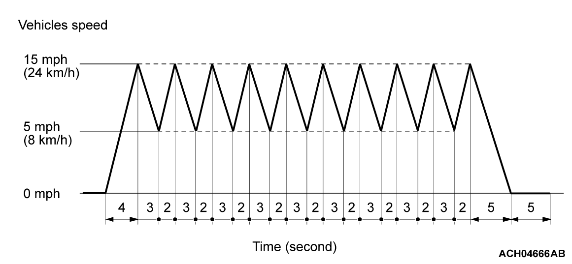
Driving pattern
Inspection conditionsUse scan tool (M.U.T.-IIISE) to check the BMU data list.
  • Item No.1 Charge state(Control): 60 % to 80 %
  • Item No.10 Module minimum temperature: -6°C (21°F) or more
Test procedure
  1. Depress the brake pedal, and turn on the power supply mode of the electric motor switch (READY operation)*.
    note*: When a DTC is set, you cannot make the READY (ready to drive) indicator illuminate by making the READY operation.
  2. Wait for 60 seconds with the accelerator pedal not depressed.
  3. Drive the vehicle in driving pattern.
  4. Turn off the power supply mode of the electric motor switch.
  5. Wait for at least 10 seconds.
  6. Perform Steps 1 to 3 again.
  7. Confirm that the DTC is not set.
 
 
PATTERN 6
Test procedure
  1. Depress the brake pedal, and turn on the power supply mode of the electric motor switch (READY operation)*.
    note*: When a DTC is set, you cannot make the READY (ready to drive) indicator illuminate by making the READY operation.
  2. Use scan tool (M.U.T.-IIISE) to execute the actuator test of the BMU (item No.1: Battery cooling fan PWM), and activate the fan motor.
  3. Wait for at least 15 seconds.
  4. Confirm that the DTC is not set.
 
 
PATTERN 7
Test procedure
  1. Depress the brake pedal, and turn on the power supply mode of the electric motor switch (READY operation)*.
    note*: When a DTC is set, you cannot make the READY (ready to drive) indicator illuminate by making the READY operation.
  2. Use scan tool (M.U.T.-IIISE) to check the BMU data list, and check that all of the following conditions are met.
    • Difference between item No.8 Module maximum temperature and item No.10 Module minimum temperature: Less than 6°C (43°F)
    • Item No.8 Module maximum temperature: Less than 30°C (86°F)
  3. Wait for at least 15 seconds.
  4. Confirm that the DTC is not set.
 
 
PATTERN 8
Test procedure
  1. Depress the brake pedal, and turn on the power supply mode of the electric motor switch (READY operation)*.
    note*: When a DTC is set, you cannot make the READY (ready to drive) indicator illuminate by making the READY operation.
  2. Use scan tool (M.U.T.-IIISE) to check the BMU data list, and check that all of the following conditions are met.
    • Difference between item No.8 Module maximum temperature and item No.10 Module minimum temperature: Less than 6°C (43°F)
    • Item No.8 Module maximum temperature: Less than 30°C (86°F)
  3. Set scan tool (M.U.T.-IIISE) to the actuator testing mode for item No.3 BAT. heating system power relay.
  4. Wait for at least 15 seconds.
  5. Confirm that the DTC is not set.