[Previous][Next]
REMOVAL AND INSTALLATION
 
 
danger
  • When servicing the high-voltage system parts, be sure to wear the specified protection equipment and disconnect the service plug to interrupt the high-voltage supply (Refer to ).
  • Do not disassemble any on board charger/DC-DC converter other than those described in this manual.
Pre-removal Operation
  • Motor Coolant Draining (Refer to GROUP 14B - On-vehicle Service, Coolant Change .)
  • Cargo Floor Box Removal (Refer to GROUP 52A - Interior Trim .)
Post-installation Operation
  • Cargo Floor Box Installation (Refer to GROUP 52A - Interior Trim .)
  • Motor Coolant Refilling (Refer to GROUP 14B - On-vehicle Service, Coolant Change .)
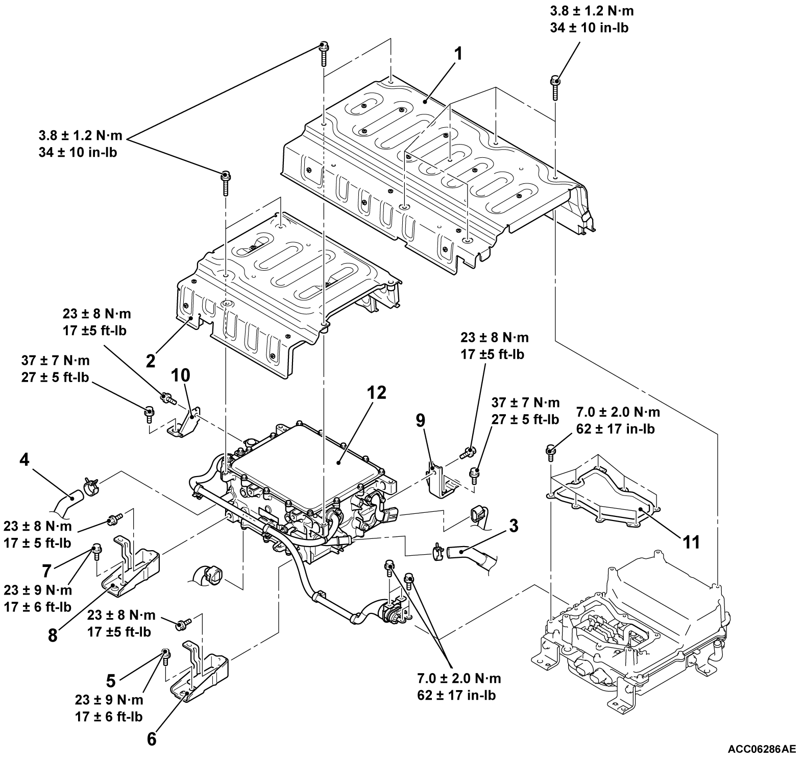
Removal steps
1.EV motor control unit cover
2.EV control unit cover
Connection connector is cut off
>>A<<3.EV radiator piping hose P
>>A<<4.EV radiator piping hose N
5.Ground bolt
6.On board charger/DC-DC converter bracket A
7.Ground bolt
8.On board charger/DC-DC converter bracket B
9.On board charger/DC-DC converter bracket C
10.On board charger/DC-DC converter bracket D
11.Removal of a terminal cover assembly of a rear motor control unit
12.On board charger/DC-DC converter


INSTALLATION SERVICE POINTS
 
 
>>A<< EV RADIATOR PIPING HOSE P, N INSTALLATION
cautionNever reuse the hose clip whose tab is broken off to prevent the rusting.
1.
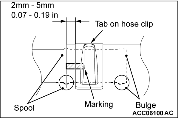
  1. Align the mating marks on the hose and hose clip.
  2. Grip the tab of the hose clip to insert the hose.
  3. Engage the hose clip.
    noteEngage the hose clip as shown.
    • The hose end should not go beyond the bulge or the spool (hose deformation).
    • Position the tab on the hose and the mark on the hose as shown.