[Previous][Next]
REMOVAL AND INSTALLATION
 
 
dangerWhen servicing the high-voltage system parts, be sure to wear the specified protection equipment and disconnect the service plug to interrupt the high-voltage supply (Refer to ).
caution
  • *: indicates parts which should be temporarily tightened, and then fully tightened with the rear motor/rear transaxle assembly weight applied on the vehicle body.
  • After adjusting the wheel alignment, always carry out calibration of the steering wheel sensor to make ASC-ECU learn the neutral point.
Pre-removal operation
  • Center exhaust pipe removal (Refer to GROUP 15 - Exhaust Pipe Main Muffler .)
  • Control link assembly, upper arm assembly, and lower arm assembly removal (Refer to GROUP 34 - Control Link, Upper Arm, and Lower Arm)
  • Motor coolant draining (Refer to GROUP 14B - On-vehicle Service, Motor Coolant Change .)
  • Transaxle oil draining (Refer to GROUP 22A - On-vehicle Service, Transaxle Fluid Change .)
  • Rear drive shaft assembly removal (Refer to GROUP 27 - Drive Shaft Assembly.)
Post-installation operation
  • Rear drive shaft installation (Refer to GROUP 27 - Drive Shaft Assembly.)
  • Transaxle oil refilling (Refer to GROUP 22A - On-vehicle Service, Transaxle Fluid Change .)
  • Motor coolant refilling (Refer to GROUP 14B - On-vehicle Service, Motor Coolant Change .)
  • Control link assembly, upper arm assembly, and lower arm assembly installation (Refer to GROUP 34 - Control Link, Upper Arm, and Lower Arm)
  • Center exhaust pipe removal (Refer to GROUP 15 - Exhaust Pipe Main Muffler .)
Removal steps
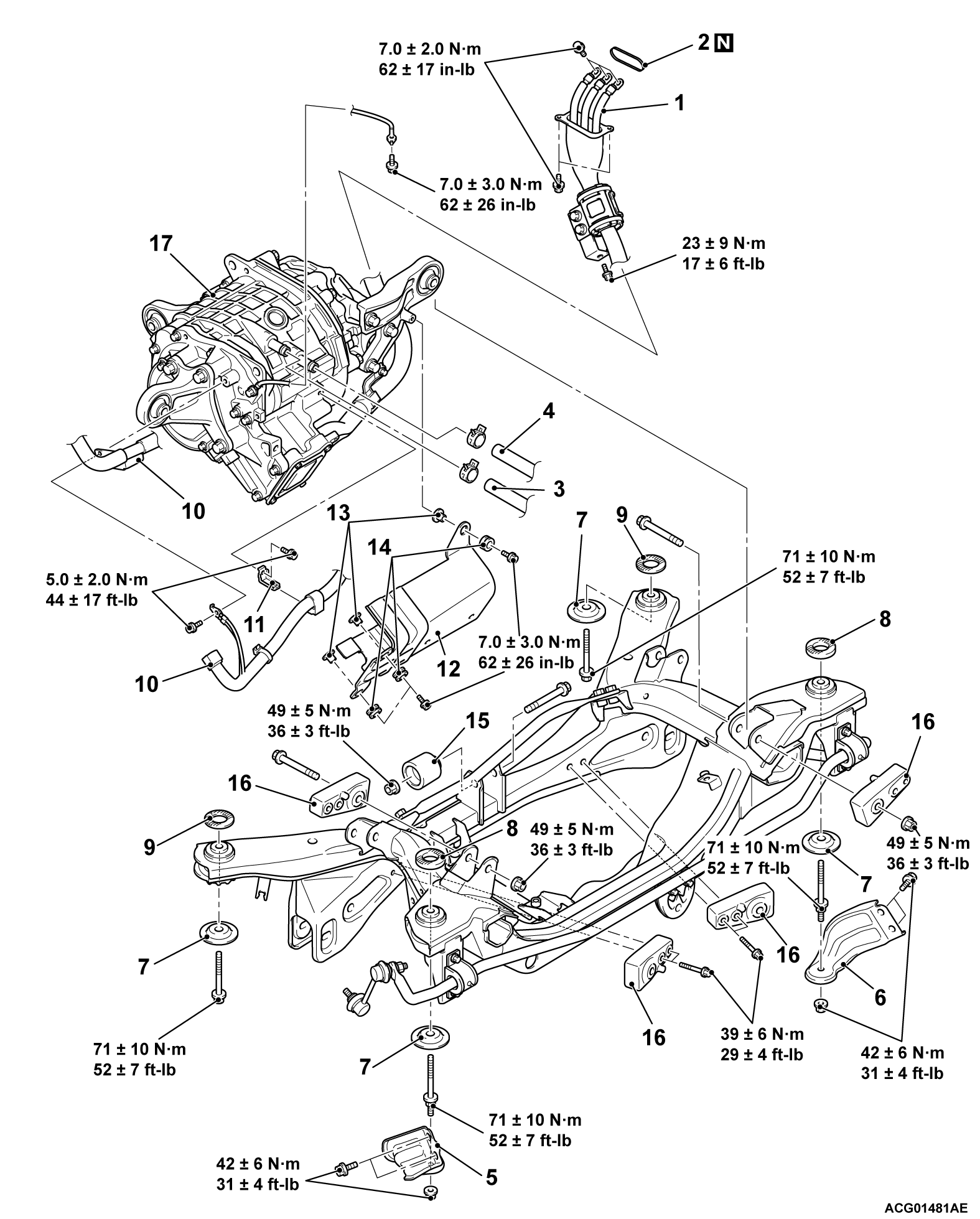
<<A>>>>B<<1.Rear motor cable connection
2.O-ring
<<B>>>>A<<3.Water hose S connection
<<B>>>>A<<4.Water hose R connection
5.Rear eye stay, rear (LH)
6.Rear eye stay, rear (RH)
7.Lower stopper
8.Stopper A
9.Stopper B
10.Rear motor wiring harness
11.Wiring harness bracket
12.Rear motor (electric motor unit) cable cover
13.Collar
14.Bushing
15.Rear differential support weight A
16.Rear differential support weight B
<<C>>17.Rear motor/rear transaxle assembly
 
 
REMOVAL SERVICE POINTS
 
 
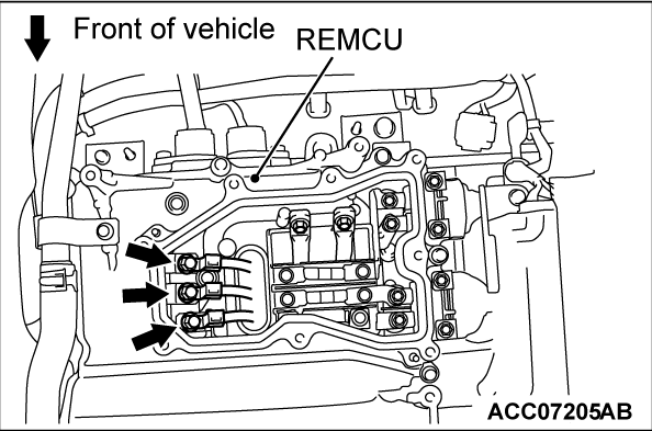
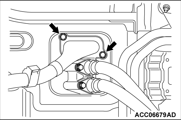
<<A>> REAR MOTOR CABLE DISCONNECTION
1. Remove the inner cable mounting bolts (3 locations).
2. Remove the outer cable mounting bolts (2 locations).
3. Pull out the cable from the REMCU.


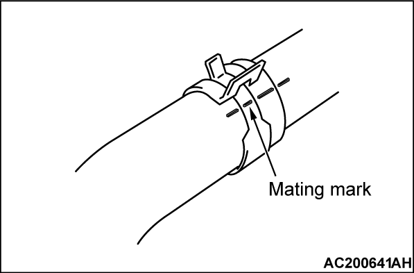
<<B>> WATER HOSES S AND R DISCONNECTION
Put a mating mark before removal as shown in the figure in order to assemble the hose and hose clips to the original positions.


<<C>> REAR MOTOR/REAR TRANSAXLE ASSEMBLY REMOVAL
1. Support the rear motor/rear transaxle assembly with a transmission jack. Remove the flange nut, the rear eye stay rear (LH), the rear eye stay rear (RH), the flange bolt, the lower stopper and the stopper.
2. Check that the hoses and wiring harness wires are not trapped. Then remove the rear motor/rear transaxle assembly with the rear motor mounting front bracket assembly, the rear motor mounting rear (LH and RH) bracket assembly attached.


INSTALLATION SERVICE POINT
 
 
>>A<< WATER HOSES S AND R CONNECTION
1. Insert the hose to each pipe up to the convex portion.
2. Align the mating marks on the hose and hose clips and install the hose without twisting the hose.


>>B<< REAR MOTOR CABLE CONNECTION
1. Connect the cable with the REMCU.
2. Install the outer cable mounting bolts and inner cable mounting bolts in this order and tighten them to the specified torque.
Tightening torque: 7.0 ± 2.0 N·m (62 ± 17 in-lb)