DIAGNOSIS CHART FOR DTC No. P0AA6-00
Inspection procedures when BMU P0AA6-00: Insulation Resistance Drop Detection Diagnosis is set.
| caution |
|
Table 1: Estimated trouble spots list
| Inspection Item | Estimated trouble spots | Action | |||||||||
| (1) Confirm the timing of when DTC No. P0AA6 is set (Refer to table 2). | (2) Measure the voltage at the service plug connector (Refer to table 3). | (3) Check the resistance at the drive battery connection (Refer to table 4). | |||||||||
| A | NG (Inside of the drive battery) | – |
| Refer to "Inspection Procedure 1: Drive battery module system" DRIVE BATTERY MODULE SYSTEM . . | |||||||
| OK | – | BMU | Recheck the DTC.
| ||||||||
| B | – | NG (Drive battery side) | Drive battery (Bus bar, drive battery high voltage connector, junction box No. 2)
| Refer to "Inspection Procedure 2: Drive battery external connection system" DRIVE BATTERY EXTERNAL CONNECTION SYSTEM . . | |||||||
| NG (Vehicle front side) |
| Refer to "Inspection Procedure 3: Front high voltage system" FRONT HIGH-VOLTAGE SYSTEM . . | |||||||||
| NG (Vehicle rear side) |
| Refer to "Inspection Procedure 4: Rear high voltage system" REAR HIGH-VOLTAGE SYSTEM . . | |||||||||
| OK | – | Recheck the DTC.
| |||||||||
| C | – | – |
| Refer to "Inspection Procedure 5: Generator system" GENERATOR SYSTEM ). ). | |||||||
| D | – | – |
| Check the insulation resistance of the electric A/C compressor (Refer to CHECK ON INSULATION RESISTANCE OF A/C COMPRESSOR ). ). | |||||||
| E | – | – |
| Perform troubleshooting of the On Board Charger (OBC)/DC-DC converter trouble symptom (Refer to TROUBLE SYMPTOM CHART ). ). | |||||||
| F | – | – |
| Refer to "Inspection Procedure 6: AC inverter system" AC INVERTER SYSTEM . . | |||||||
| G | – | – |
| Refer to "Inspection Procedure 7: Motor system" MOTOR SYSTEM . . | |||||||
(1) Confirm the timing of when DTC No. P0AA6-00 is set.
1. Open hood, back door, rear left side door or rear right side door. (After that, work in the open state until instructed.)
2. Change the power supply mode of the electric motor switch to OFF from ON condition, then wait for 3 minutes or more in key lock condition. (Check that the P indicator on the selector lever turns off.)
3. Connect the M.U.T.-IIISE with the power supply mode of the electric motor switch changed to OFF.
4. Change the power supply mode of the electric motor switch to ON (READY indicator: OFF).
5. On the system selection screen of the M.U.T.-IIISE, select "BMS".
6. Erase the DTC using self-diagnosis function.
7. Satisfy the confirmation conditions and confirmation time in the table below from the top, and check the timing of when the DTC No. P0AA6-00 is set again.
Table 2 Confirming the timing of when the DTC No. P0AA6-00 is set
| note | *: The A/C compressor does not operate in the following conditions.
|
(2) Measure the voltage at the service plug connector.
| danger | When servicing the high voltage system parts, always wear the specified protective gears, and shut off the high voltage by removing the service plug. |
1. Remove the service plug from the service plug box (Refer to PRECAUTIONS ON HOW TO USE THE HIGH-VOLTAGE VEHICLE ).
).
 ).
).| danger | Do not use the special tool electric insulation tester (MB992355) to measure the insulation resistance at the service plug connector. If used, the BMU may be damaged. |
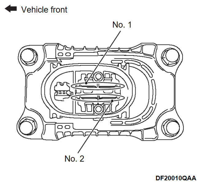
2. Measure the voltage between the following terminals on the service plug box assembly using a high voltage multimeter.
| note | Judge by the voltage value after 1 minute or more has passed from the start of measurement. |
Table 3 Measure the voltage at the service plug connector.
(3) Check the resistance at the drive battery connection.
| danger | When servicing the high voltage system parts, always wear the specified protective gears, and shut off the high voltage by removing the service plug. |
1. Disconnect the drive battery front cable and drive battery rear cable (junction box) from the drive battery.
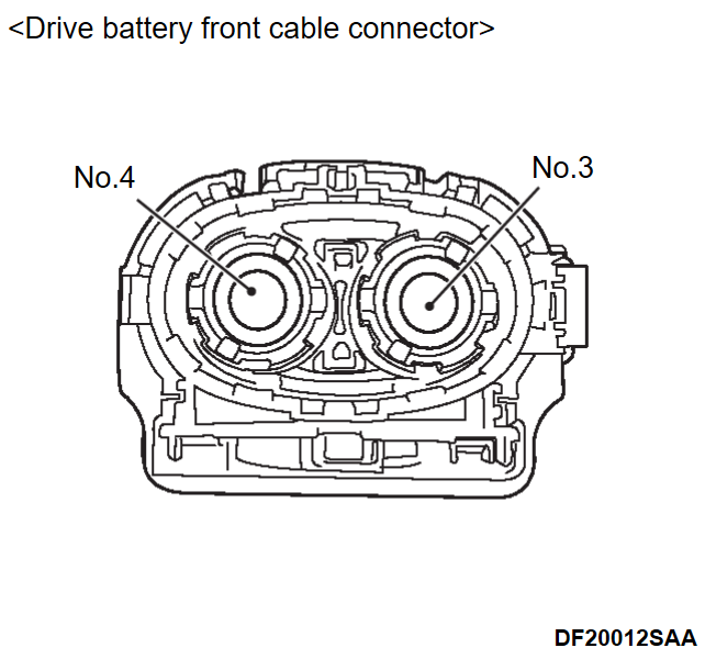
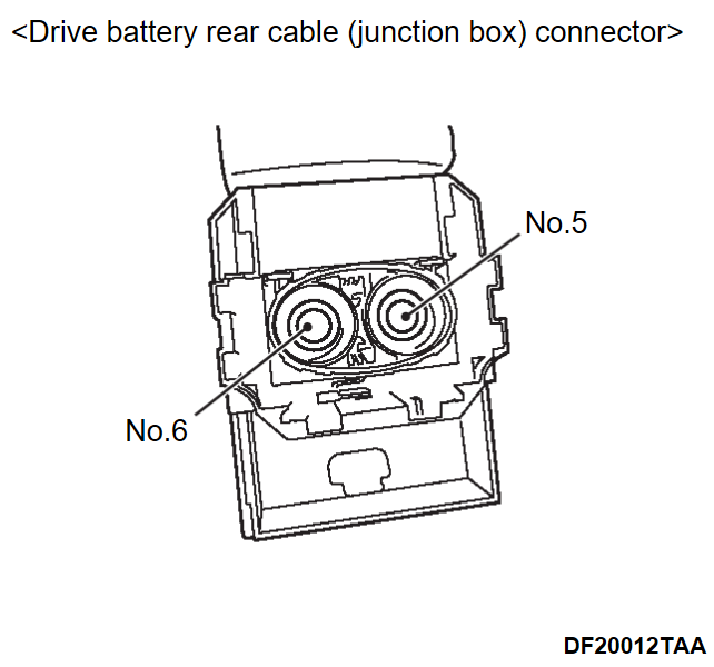
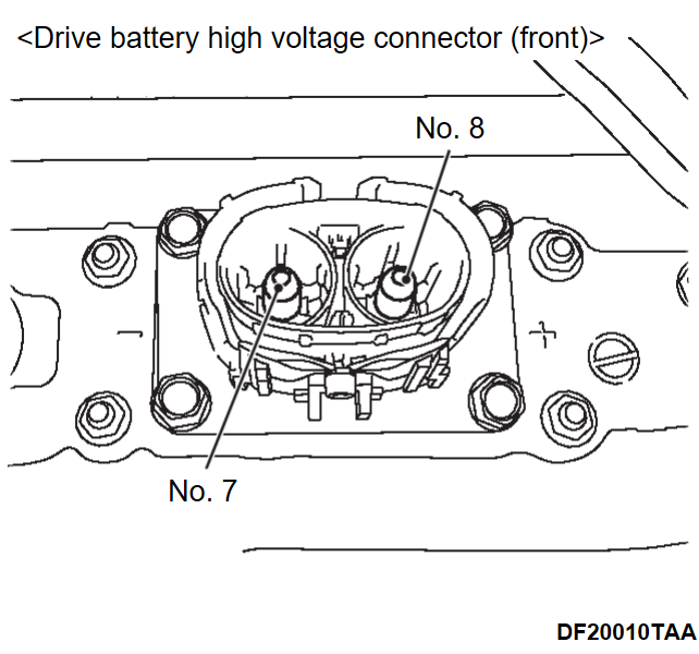
2. Measure the insulation resistance at the following terminals on the drive battery front cable side, drive battery rear cable (junction box) side and drive battery side using the special tool electric insulation tester (MB992355).
Table 4 Check the resistance at the drive battery connection.
![[Previous]](../../../buttons/fprev.png)
![[Next]](../../../buttons/fnext.png)


