PRECAUTIONS ON HOW TO USE THE HIGH-VOLTAGE VEHICLE
This vehicle has a high-voltage circuit of 350 V (nominal value) (Depending on the remaining capacity of the battery, generate a maximum operating voltage of 650 V). If the vehicle is handled incorrectly, electric leakage or shock may result. Also, the service technicians/engineers who perform inspection and service related to the high-voltage circuit of the electric vehicles are obligated to observe the legal requirements of your country/local area.
INSPECTION/TEST OF PROTECTIVE EQUIPMENT, BLOTTER STORAGE
Check and store the protective equipment in accordance with the legal requirements of your country/local area.
PROTECTIVE EQUIPMENT
| caution |
|
| Protective equipment | Name | Use |
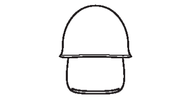
| Electric insulation helmet (with shield) |
| |
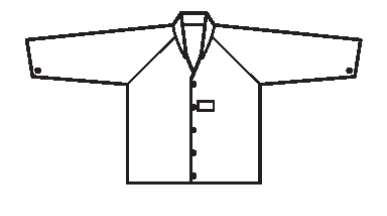
| Electric insulation jacket |
| |
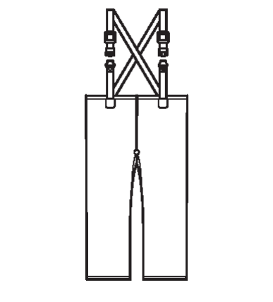
| Electric insulation trousers |
| |
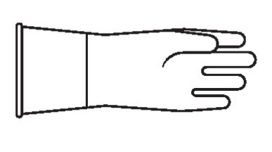
| Electric insulation glove |
| |
| Electric insulation boots |
|
TESTER AND SPECIAL TOOL
Be sure to use the tester and special tools specified in this manual.
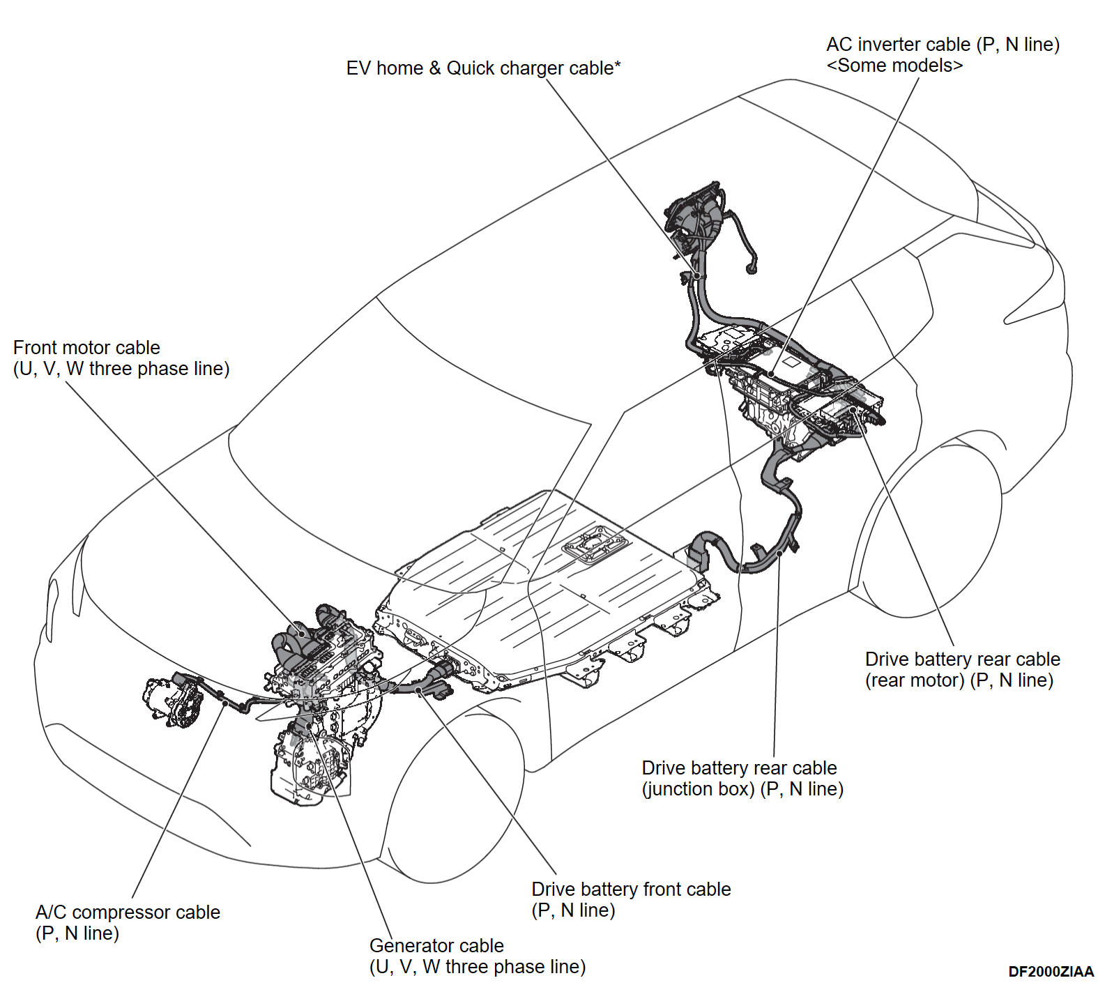
HIGH-VOLTAGE COMPONENTS
The high-voltage components are described below. Also, wiring harness and connectors of high-voltage circuit are unified with a color of orange.
- Drive battery [with built-in Battery Management Unit (BMU)]
- Power Drive Unit (PDU) [with built-in Front electric motor control unit (FEMCU) and Generator Control Unit (GCU)]
- Front motor
- Rear motor [with built-in Rear Electric Motor Control Unit (REMCU)]
- Generator
- On Board Charger (OBC)/DC-DC converter
- AC inverter <Some models>
- Drive battery cable
- EV home & Quick charger cable*
- Service plug
- Wiring harness and connector
- A/C compressor
- Junction box
- High voltage sensor (for quick charging)
| note | *: Quick charger cable is only equipped on models with quick charging system. |
SERVICE PRECAUTIONS
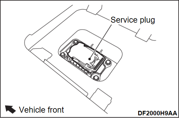
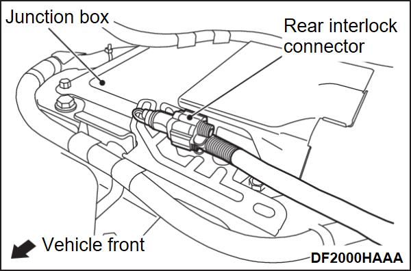
Remove the service plug under the rear center seat and disconnect the rear interlock connector under the luggage room by following the procedures below to shuts off the high-voltage to the high-voltage system. Also, when installing the service plug and the service lid, check the precautions.
SERVICE PLUG AND SERVICE LID REMOVAL STEPS
Prepare the service plug removal steps check sheet (Refer toSERVICE PLUG REMOVAL STEPS CHECK SHEET .)
.)
 .)
.)1. Disconnect the charge connector if the vehicle is being charged.
2. Turn OFF the power supply mode of the electric motor switch.
3. Open the hood and back door.
4. Press the electric motor switch once to turn ON the power supply mode, then press and hold the electric motor switch for 5 seconds or more.
5. Close the driver's side front door, and wait for 5 minutes or more.
6. Check that the combination meter turns off, and the P indicator on the parking lock switch turns off.
7.
| warning |
|
Disconnect the negative terminal of the 12V battery, and wait for 5 minutes or more.
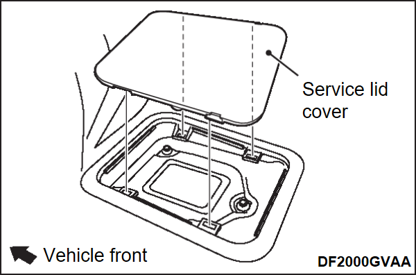
8. Remove the service lid cover.
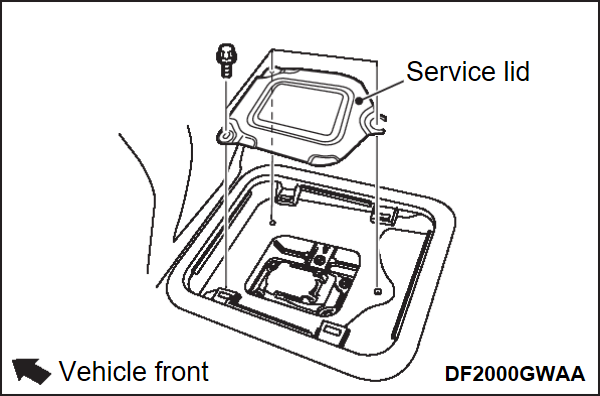
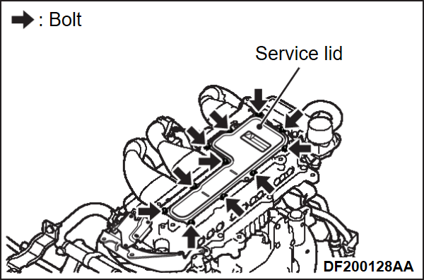
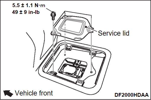
9. Remove the service lid mounting bolts, and then remove the service lid.
10.
| danger |
|
| warning | The voltage of the smooth condenser in the inverter must be decreased thoroughly. Therefore, do not remove the service plug for 5 minutes after the negative terminal of the 12V battery is disconnected. |
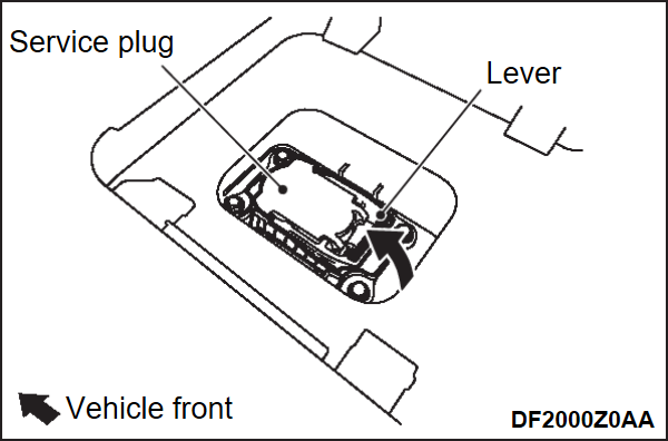
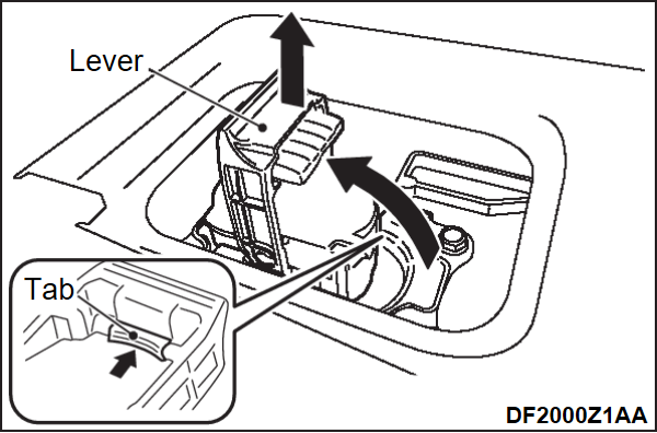
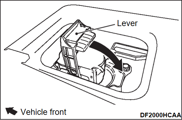
Pull up the service plug lever a little, then pull up the lever more while pushing the tab, then pull out the service plug.
11.
| danger | After removing the service plug, insulate the plug installed part of the drive battery side securely. |
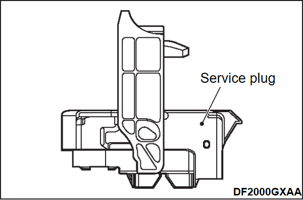
Remove the service plug.
12.
| danger | During inspection, wear the electric insulation gloves. If the high-voltage cannot be shut off after the inspection, refer to "Action when High Voltage Cannot Be Shut Off". |
When removing and installing each high-voltage part, be sure to perform the following inspection beforehand.
When the drive battery is removed and installed
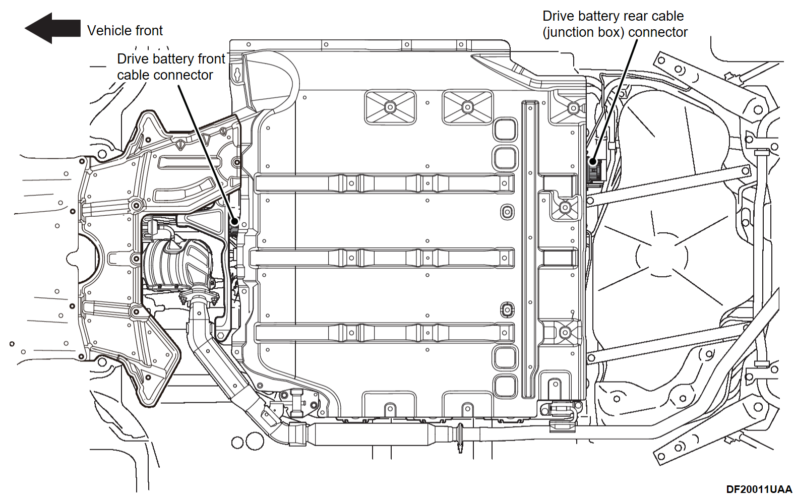
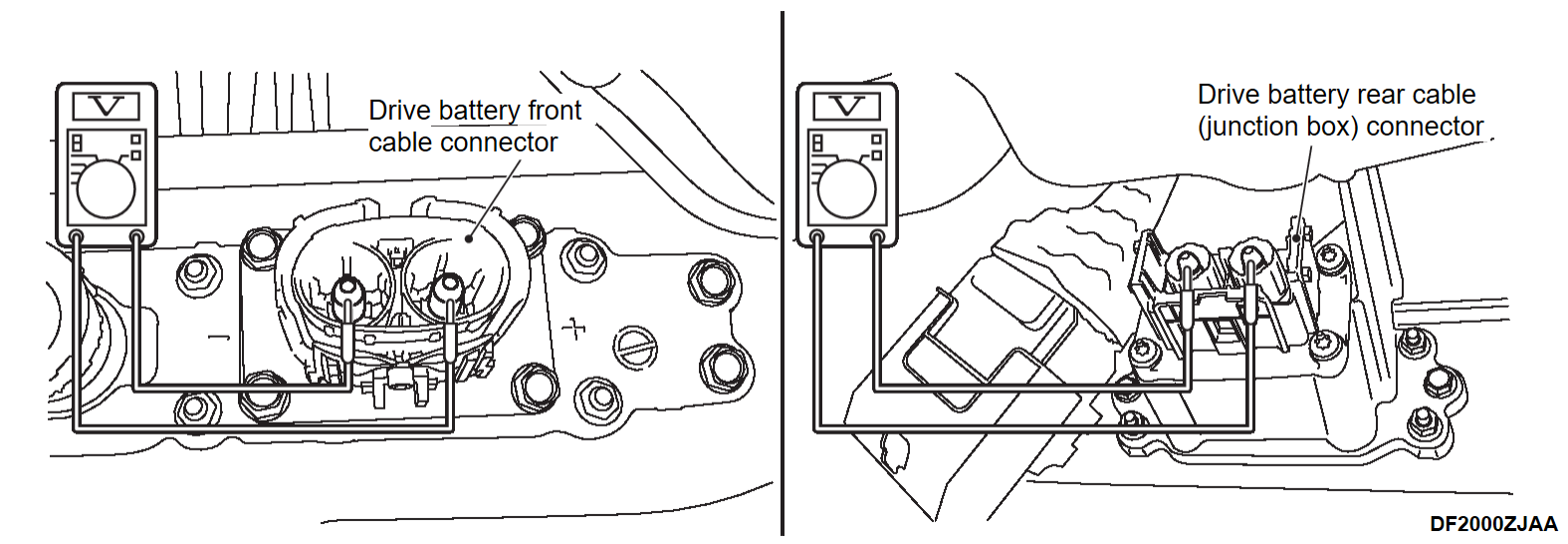
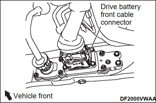
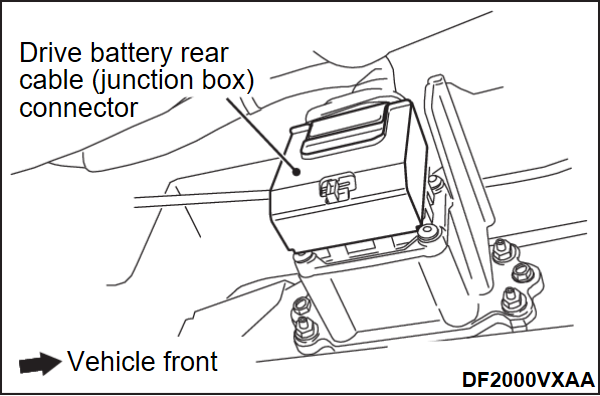
- Check the drive battery front cable connector and drive battery rear cable (junction box) connector by following the procedures below.
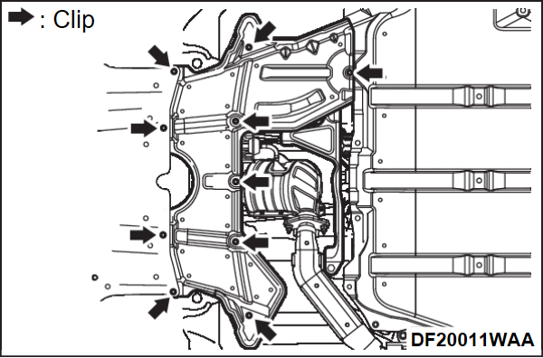
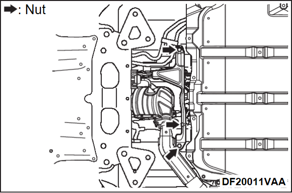
- Remove the engine room under cover rear (Refer to Exterior - Engine Under CoverRemoval and Installation
 ).
). - Remove the front floor heat protector (rear) (Refer to Battery Management Unit (BMU) and Drive Battery - Drive BatteryDRIVE BATTERY REMOVAL AND INSTALLATION
 ).
). - Disconnect the drive battery front cable and drive battery rear cable (junction box) from the drive battery, and measure the voltages between the terminals as shown in the illustration using a high-voltage multimeter.Normal voltage: Approximately 0 V
note For disconnecting the drive battery front cable connector and drive battery rear cable (junction box) connector, refer to "High-voltage Cable Connector Removal Steps". - As the result of the voltage measurement, if the high-voltage is judged that it is not shut off, the internal malfunction of the drive battery may be suspected. Be very careful and remove the drive battery.
- Remove the engine room under cover rear (Refer to Exterior - Engine Under CoverRemoval and Installation
- Check the drive battery front cable connector and drive battery rear cable (junction box) connector by following the procedures below.
When the other high-voltage parts are removed and installed
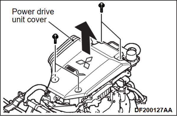
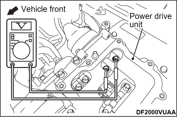
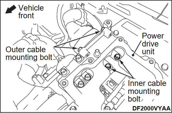
- Remove the power drive unit cover inside the engine compartment.
- Remove the service lid of the power drive unit.
- Using a high-voltage multimeter, measure the voltages between the terminals as shown in the illustration.Normal voltage: Approximately 0 V
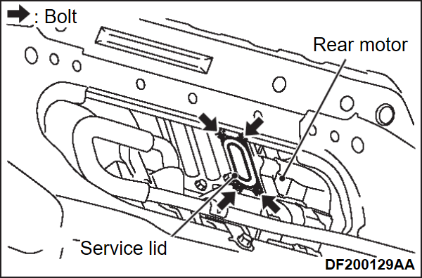
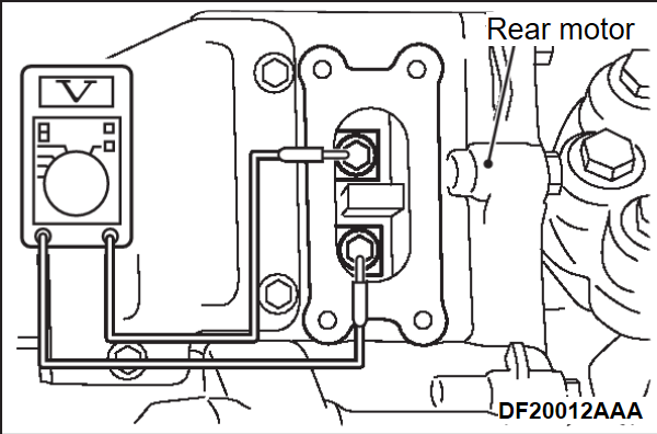
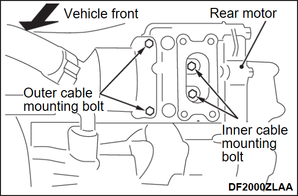
- Remove the service lid on the rear side of the rear motor.
- Using a high-voltage multimeter, measure the voltages between the terminals as shown in the illustration.Normal voltage: Approximately 0 V
- As the result of the voltage measurement, if the high-voltage is judged that it is not shut off, perform "Action when High Voltage Cannot Be Shut Off" (
 ) to secure the safety before servicing.
REAR INTERLOCK CONNECTOR DISCONNECTION STEPS
When servicing the junction box, On Board Charger (OBC)/DC-DC converter, and AC inverter, disconnect the rear interlock connector in addition to the service plug removal.
1. Remove the service plug.
2. Remove the EV control unit cover (LH) and (RH) (Refer toON BOARD CHARGER (OBC) &DC-DC CONVERTER REMOVAL AND INSTALLATION ).
).
 ).
).3. Disconnect the rear interlock connector.
SERVICE PLUG AND SERVICE LID INSTALLATION STEPS
| danger | Wear the electric insulation gloves when installing the service plug. |
1. Install the service plug.
| caution | Pull the service plug lever down until it clicks, because the interlock switch does not operate unless the service plug lever is pulled down properly. |
2. Tighten the service lid mounting bolts to the specified torque.
3. Insert the 4 tabs of the service lid cover securely to install the service lid cover.
ACTION WHEN HIGH VOLTAGE CANNOT BE SHUT OFF
Tool
| caution |
|
| Tool | Name | Use | ||
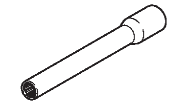
| Electric insulation socket |
|
| danger | Be sure to wear the electric insulation gloves during this work. |
| danger | Be sure to use the electric insulation socket during this work. |
When the high voltage remains even after the shut-off of the high voltage is performed, or when the high voltage shut-off work itself is difficult because of the accidental damages, perform the security according to the following procedure.
1. For disconnecting the drive battery front cable connector and drive battery rear cable (junction box) connector from the drive battery side (Refer to "High-voltage Cable Connector Removal Steps").
2. If steps 1 is difficult to perform or it is necessary to carry out any service work in the engine compartment or the electric motor unit compartment, disconnect the drive battery cable at the power drive unit side or REMCU side (Refer toPOWER DRIVE UNIT REMOVAL AND INSTALLATION ,POWER DRIVE UNIT REMOVAL AND INSTALLATION
 ).
).
 ,POWER DRIVE UNIT REMOVAL AND INSTALLATION
 ).
).ACTION WHEN HIGH-VOLTAGE SHUT-OFF SYSTEM IS OPERATED
A high-voltage shut-off system isolates high voltage in the event of a crash. When this system operates, diagnose the post-collision vehicles (Refer to SRS Airbag Control System - Work FlowWork Flow ). After the diagnosis, also erase the PHEV-ECU related DTC.
 ). After the diagnosis, also erase the PHEV-ECU related DTC.
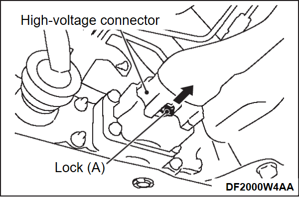
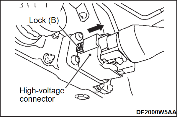
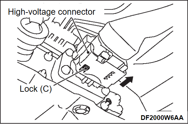
HIGH-VOLTAGE CABLE CONNECTOR (DRIVE BATTERY FRONT CABLE AT DRIVE BATTERY SIDE) REMOVAL STEPS
| danger |
|
| caution | When unlocking the connector lock, do not use tools etc. otherwise the connector lock may be damaged. Be sure to unlock the connector lock by hands. |
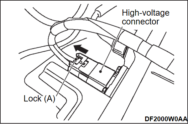
1. Move the lock (A) of the connector to the direction of the arrow.
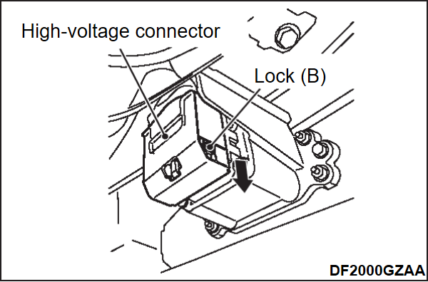
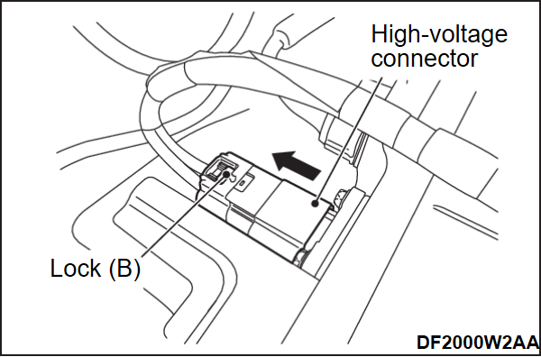
2. Pull the connector to the direction of the arrow until it stops while pushing the lock (B).
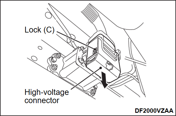
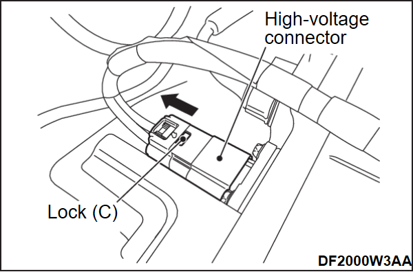
3. Pull the connector to the direction of the arrow while pushing the lock (C) to disconnect the connector.
HIGH-VOLTAGE CABLE CONNECTOR [DRIVE BATTERY REAR CABLE (JUNCTION BOX) AT DRIVE BATTERY SIDE] REMOVAL STEPS
| danger |
|
| caution | When unlocking the connector lock, do not use tools etc. otherwise the connector lock may be damaged. Be sure to unlock the connector lock by hands. |
1. Move the lock (A) of the connector to the direction of the arrow (UNLOCK position).
2. Pull down the connector to the direction of the arrow until it stops while pushing the lock (B).
3. Pull the connector to the direction of the arrow while pushing the lock (C) to disconnect the connector.
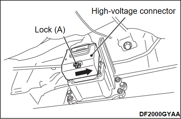
HIGH-VOLTAGE CABLE CONNECTOR [CABLE BETWEEN JUNCTION BOX AND AC INVERTER] REMOVAL STEPS
| danger |
|
| caution | When unlocking the connector lock, do not use tools etc. otherwise the connector lock may be damaged. Be sure to unlock the connector lock by hands. |
1. Move the lock (A) of the connector to the direction of the arrow.
2. Pull the connector to the direction of the arrow until it stops while pushing the lock (B).
3. Pull the connector to the direction of the arrow while pushing the lock (C) to disconnect the connector.
![[Previous]](../../../buttons/fprev.png)
![[Next]](../../../buttons/fnext.png)
