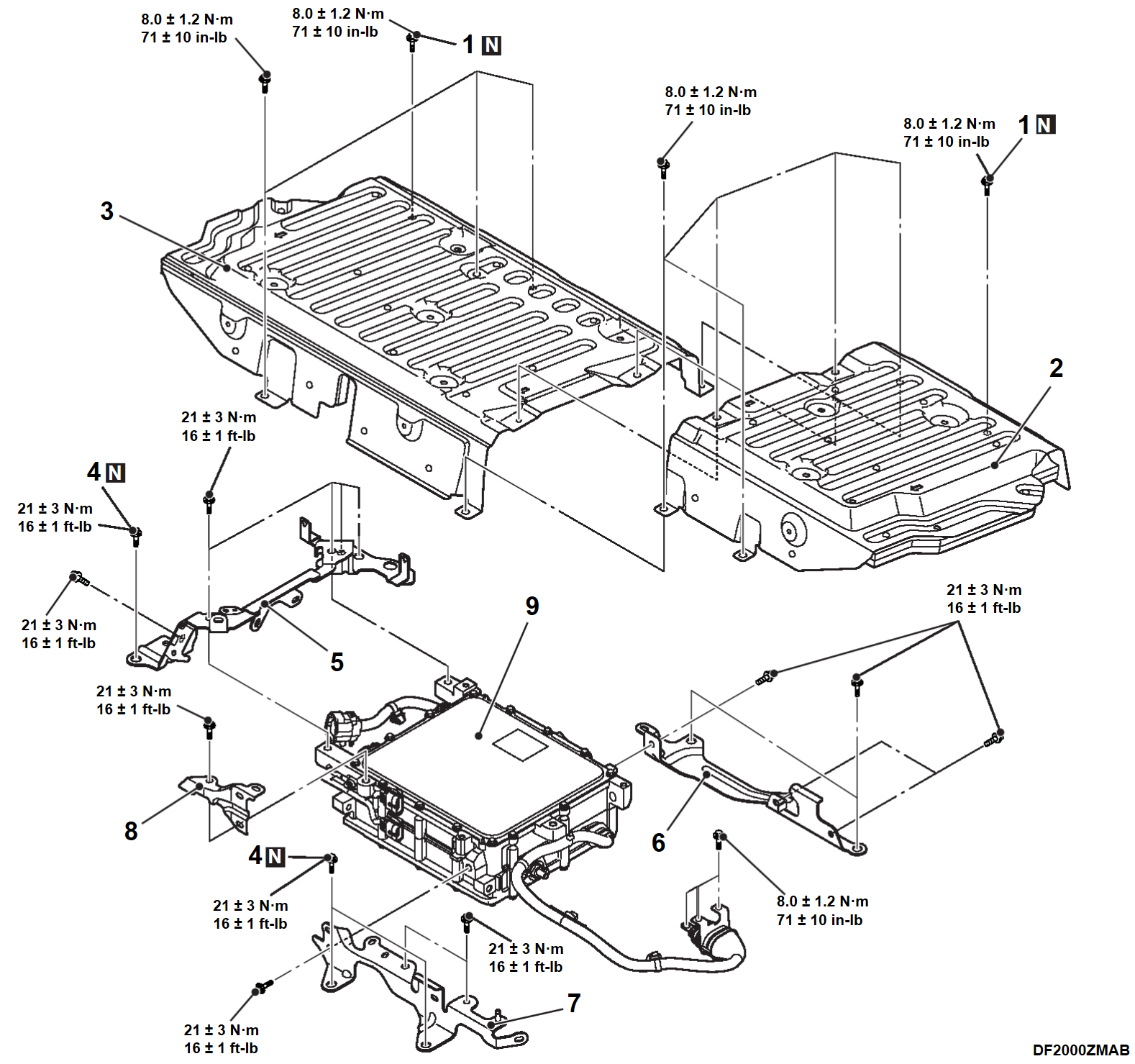
REMOVAL AND INSTALLATION
| danger |
|
Pre-removal and Post-installation Operation
|
|
REMOVAL SERVICE POINT
<<A>> ON BOARD CHARGER (OBC)/DC-DC CONVERTER REMOVAL
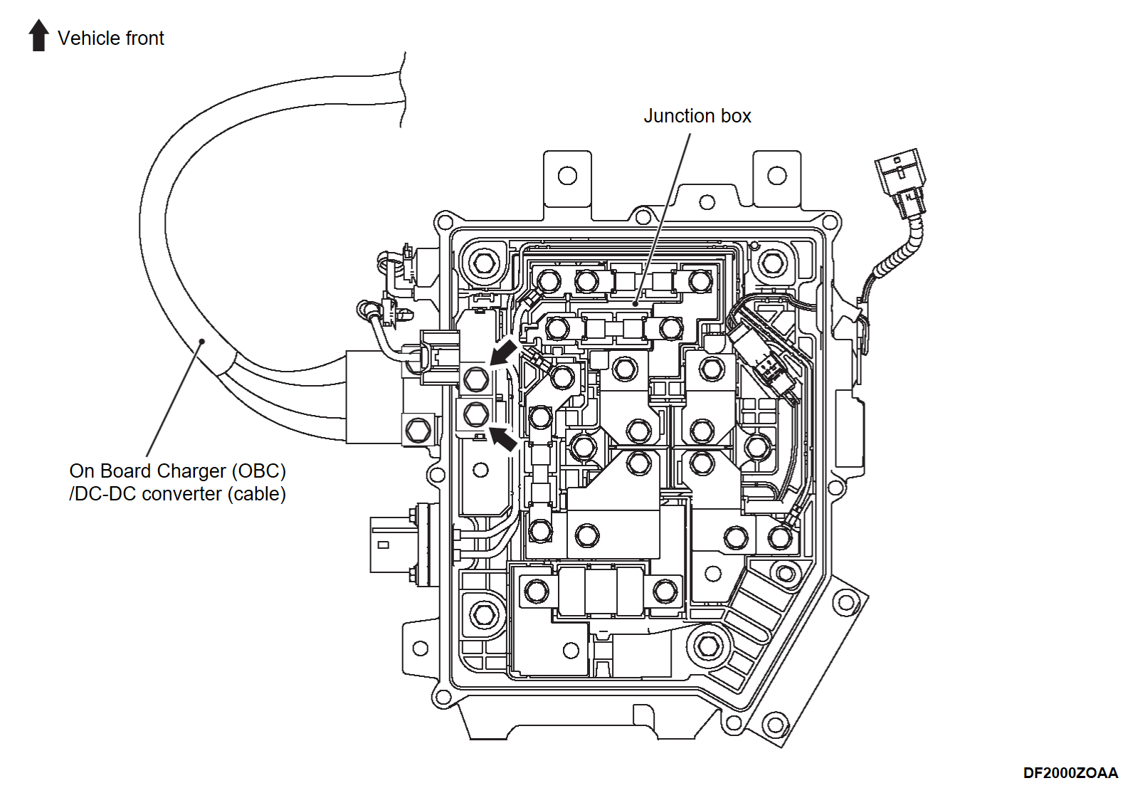
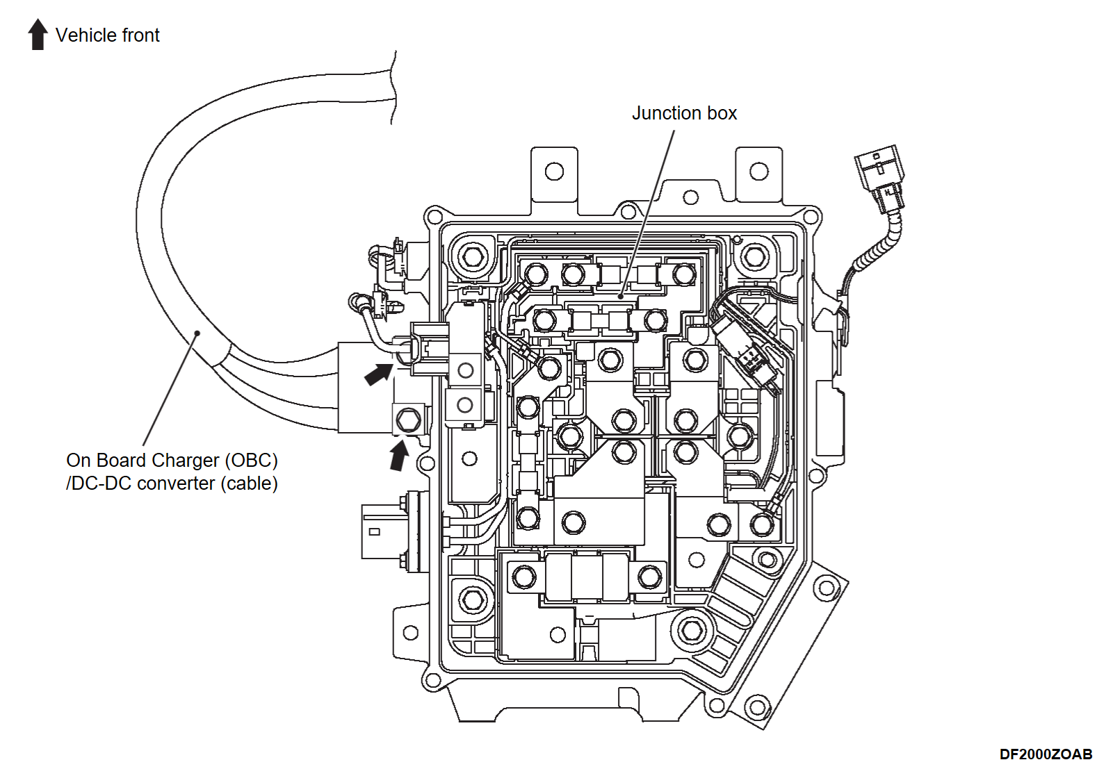
When remove the On Board Charger (OBC)/DC-DC converter, follow the below steps to disconnect the cable
1. Remove the inner cable mounting bolts (2 places).
2. Remove the outer cable mounting bolts (2 places).
3. Pull out the On Board Charger (OBC)/DC-DC converter cable from the junction box.
INSTALLATION SERVICE POINT
>>A<< ON BOARD CHARGER (OBC)/DC-DC CONVERTER INSTALLATION
When install the On Board Charger (OBC)/DC-DC converter, follow the below steps to connect the cable
1. Install the cable to the junction box.
2. Install the outer cable mounting bolts and inner cable mounting bolts in this order, and tighten with the specified torque.
Tightening torque: 8.0 ± 1.2 N·m (71 ± 10 in-lb)
![[Previous]](../../../buttons/fprev.png)
![[Next]](../../../buttons/fnext.png)


