Removal and Installation
REMOVAL
| note | When removing the timing chain, remove the engine assembly from the vehicle. |
ELECTRIC INTAKE VALVE TIMING CONTROL ACTUATOR
1. Remove reservoir tank. Refer to Exploded View.Exploded View

2. Support the bottom surface of engine using a transmission jack, and then remove the rear torque rod and the engine mounting insulator (RH). Refer to Removal and Installation .
.
 .
.| caution | When using the jack, apply a piece of wood to the oil pan (lower) mounting bolt to protect the bottom of engine from being scratched. |
3. Disconnect the harness connectors from the electric intake valve timing control actuator.
EXHAUST VALVE TIMING INTERMEDIATE LOCK CONTROL SOLENOID VALVE AND EXHAUST VALVE TIMING CONTROL SOLENOID VALVE
1. Remove the engine under cover. Refer to Removal and Installation .
.
 .
.2. Disconnect the harness connectors from the exhaust valve timing intermediate lock control solenoid valve and exhaust valve timing control solenoid valve.
3. Remove bolts and remove the exhaust valve timing intermediate lock control solenoid valve and exhaust valve timing control solenoid valve.
| caution | Do not reuse O-rings. |
TIMING CHAIN
| caution | Apply new engine oil to parts as indicated in the illustration before installation. |
1. Remove the engine assembly from the vehicle. Refer to Removal and Installation.Removal and Installation

2. Secure the engine assembly to stand. Refer to Setting.Setting

3. Remove the intake manifold. Refer to Removal and Installation.Removal and Installation

4. Remove intake port insulator. Refer to Removal and Installation .
.
 .
.| caution | Do not reuse intake port insulator gasket. |
5. Remove the oil pan (upper). Refer to Removal and Installation.Removal and Installation

6. Set the No.1 cylinder at TDC on the compression stroke using the following procedure:
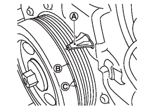
- Rotate the crankshaft pulley clockwise and align the mating mark
 to the timing indicator
  on the front cover.
note Do not use white marks  when setting TDC.
 - Remove the engine oil gauge.
- Remove the high pressure fuel pump insulator. Refer to Removal and Installation.Removal and Installation

- Disconnect the harness connectors from the ignition coils.
- Remove the ignition coils. Refer to Removal and Installation.Removal and Installation

- Disconnect harness retainers from rocker cover.
- Unbolt and reposition engine cover bracket.(With engine cover models) Refer to Removal and Installation.
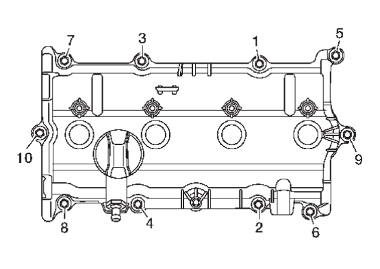
- Loosen rocker cover bolts in reverse of the sequence shown and remove the rocker cover.
caution Do not reuse the rocker cover gasket. - At this time, check that the both intake camshaft
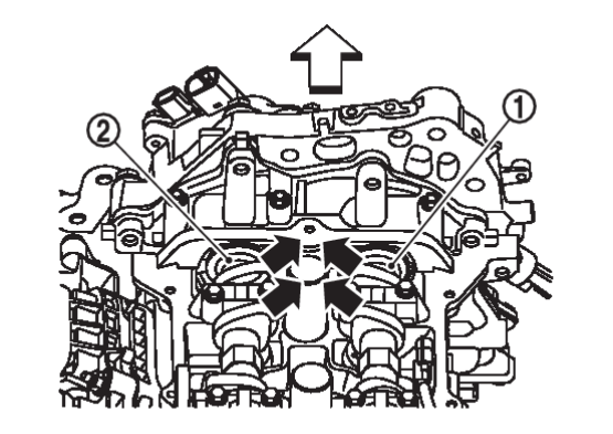
 and exhaust camshaft
  cam lobes of No. 1 cylinder are oriented (
 ) as shown.
: Engine front - If not, rotate crankshaft pulley one revolution (360 degrees) and align as shown.
7. Disconnect the harness connectors from the exhaust valve timing intermediate lock control solenoid valve and exhaust valve timing control solenoid valve, electric intake valve timing control actuator and engine oil pressure sensor.
8. Remove the engine oil pressure sensor (if necessary).
9. Remove the exhaust valve timing intermediate lock control solenoid valve and exhaust valve timing control solenoid valve (if necessary).
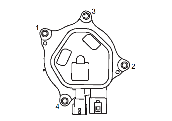
10. Loosen electric intake valve timing control actuator bolts in reverse of the sequence shown and remove electric intake valve timing control actuator.
11. Unbolt ground cable and release harness retainers from front cover then reposition harness.
12. Remove the drive belt auto tensioner. Refer to Removal and Installation.Removal and Installation

13. Remove the fuel rail protector. Refer to Removal and Installation .
.
 .
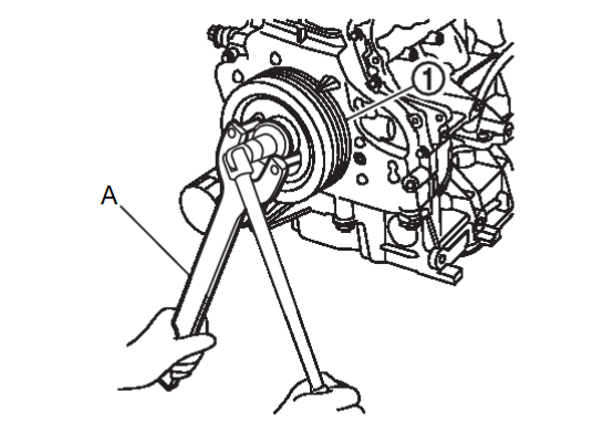
.14. Remove crankshaft pulley  using the following procedure:
 using the following procedure:
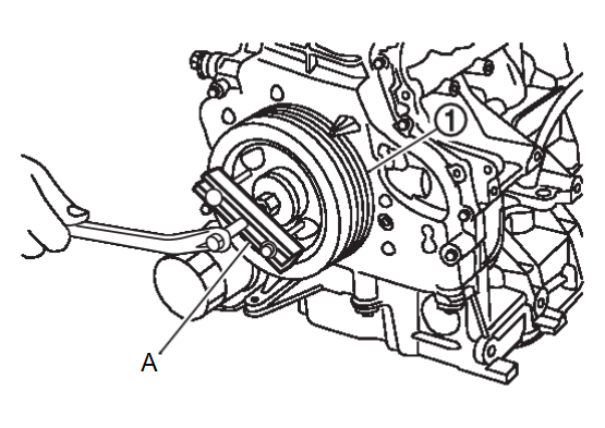
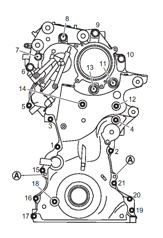
15. Remove the front cover using the following procedure:
- Loosen front cover bolts in reverse of the sequence shown.

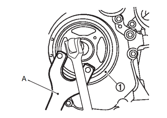
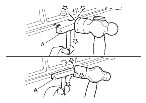
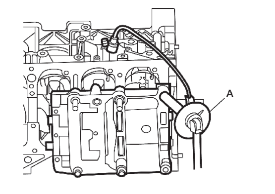
: Dowel pin - Cut liquid gasket using seal cutter [SST: KV10111100 (J-37228)] (A).
caution Do not damage the front cover. - Remove the front cover.
caution Do not reuse O-rings or filter. - Remove front oil seal using suitable tool.
caution - Do not damage the front cover.
- Do not reuse front oil seal.
- Remove the camshaft sprocket (INT) oil seal from the front cover (if necessary).
caution Do not reuse camshaft sprocket (INT) oil seal if removed from front cover. - Remove the tension guide (upper) from the front cover (if necessary).
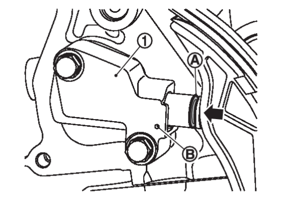
16. Remove timing chain tensioner using the following procedure:
- Push in timing chain tensioner
 plunger until groove
  is aligned with hole
  in tensioner body.
- Insert a suitable tool into hole to secure plunger.
- Remove the timing chain tensioner.
caution Do not remove suitable tool from timing chain tensioner when removed from vehicle. If timing chain tensioner plunger becomes fully extended, replace timing chain tensioner.
18. Remove the timing chain  .
.
 .
.| caution | Do not rotate the crankshaft or camshafts while the timing chain is removed. It can cause damage to the valve and piston. |
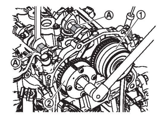
19. Remove the camshaft sprockets using the following procedure (if necessary):
20. Remove balancer unit timing chain tensioner using the following procedure:
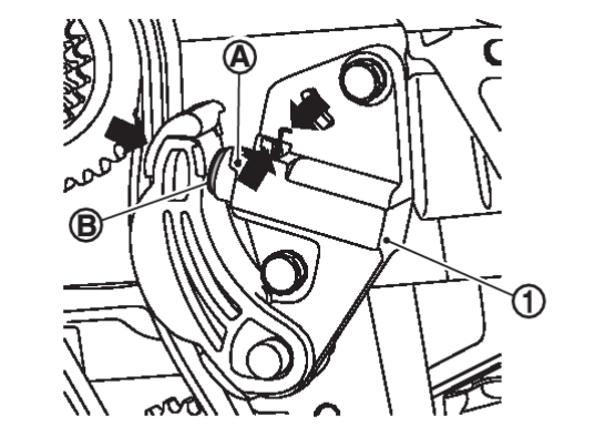
- Compress clip and push in on tensioner plunger.Push plunger in until the end of the plungeris aligned with the holein the balancer unit timing chain tensioner body.
caution Do not remove suitable tool from timing chain tensioner when removed from vehicle. If timing chain tensioner plunger becomes fully extended, replace timing chain tensioner. - Remove the balancer unit timing chain tensioner.
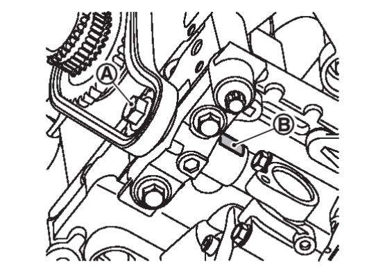
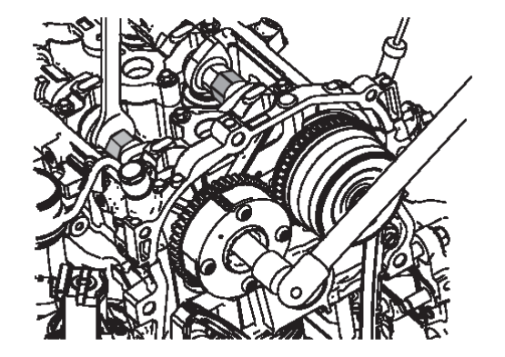
21. Secure width across flats  of the balancer unit LH side shaft using a suitable tool. Loosen the balancer unit sprocket bolt
  .
.
 of the balancer unit LH side shaft using a suitable tool. Loosen the balancer unit sprocket bolt
  .
.22. Remove balancer unit timing chain, balancer unit sprocket and crankshaft sprocket.
INSTALLATION
ELECTRIC INTAKE VALVE TIMING CONTROL ACTUATOR
Installation is in the reverse order of removal.
EXHAUST VALVE TIMING INTERMEDIATE LOCK CONTROL SOLENOID VALVE AND EXHAUST VALVE TIMING CONTROL SOLENOID VALVE
Installation is in the reverse order of removal.
| caution | Do not reuse O-rings. |
TIMING CHAIN
1. Make sure the crankshaft key points straight up.
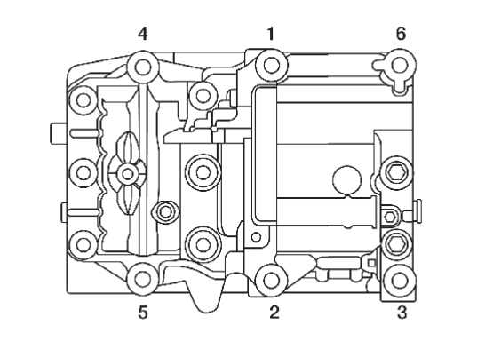
2. Install the balancer unit and tighten the bolts in the numerical order as shown:
| caution |
|
| Step 1 | Bolts 1-5 | : 42 N·m (4.3 kg-m, 31 ft-lb) |
| Bolt 6 | : 36 N·m (3.7 kg-m, 27 ft-lb) | |
| Step 2 | Bolts 1-5 | : 120° – 125° |
| Bolt 6 | : 90° – 95° | |
| Step 3 | Loosen in reverse order | : 0 N·m (0 kg-m, 0 ft-lb) |
| Step 4 | Bolts 1-5 | : 42 N·m (4.3 kg-m, 31 ft-lb) |
| Bolt 6 | : 36 N·m (3.7 kg-m, 27 ft-lb) | |
| Step 5 | Bolts 1-5 | : 120° – 125° |
| Bolt 6 | : 90° – 95° |
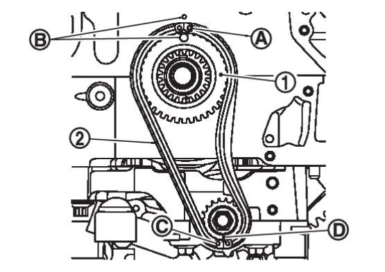
3. Install the crankshaft sprocket  and the balancer unit timing chain
  .
.
 and the balancer unit timing chain
  .
.- Make sure that the crankshaft sprocket is positioned with mating marks
 on the block and sprocket meeting at the top.
 - Install it by lining up mating marks on each sprocket
 ,
,  and timing chain
  ,
,  .
.
 | : Pink link |
 | : Blue link |
4. Install timing chain tensioner and remove suitable tool.
- Check matching mark position of balancer unit drive chain and each sprocket again.
5. If removed, install camshaft sprockets.
6. Install the timing chain using the following procedure:
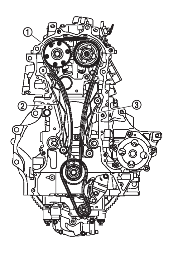
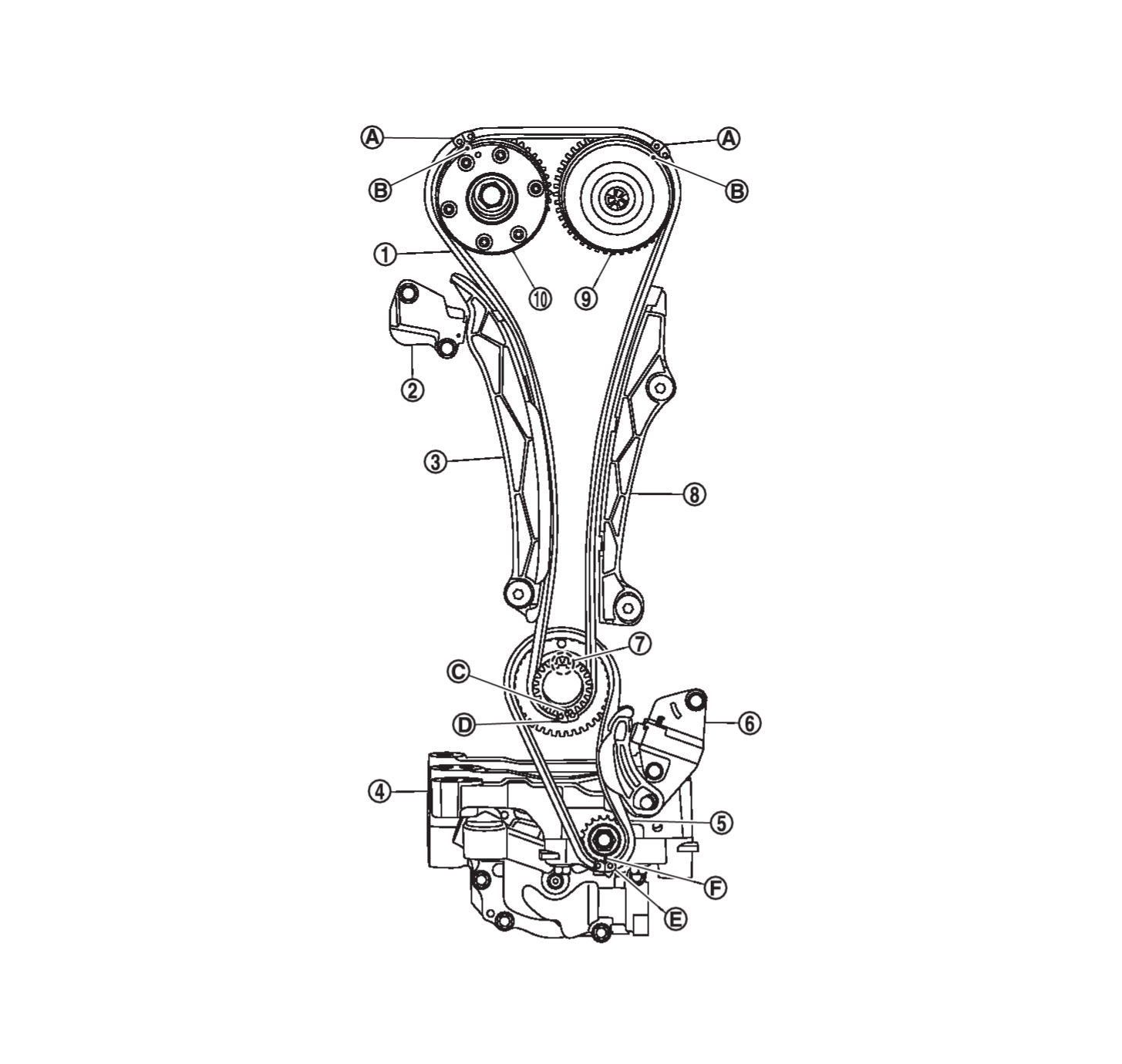
(1) Align the matching marks of each sprocket with the matching marks of timing chain.
 | Timing chain |  | Timing chain tensioner |  | Slack guide |
 | Balancer unit |  | Balancer unit timing chain |  | Balancer unit timing chain tensioner |
 | Crankshaft key |  | Tension guide |  | Camshaft sprocket (INT) |
 | Camshaft sprocket (EXH) | ||||
 | Orange link |  | Timing mark |  | Sprocket timing mark |
 | Pink link |  | Blue link |  | Timing mark |
| caution | Check matching mark position of each sprocket and timing chain again after installing the timing chain. |
| note | If these matching marks are not aligned, rotate the camshaft slightly by holding the hexagonal portion to correct the position. |
(3) Install the timing chain tensioner and remove suitable tool.
| caution | Do not remove suitable tool from timing chain tensioner when removed from vehicle. If timing chain tensioner plunger becomes fully extended, replace timing chain tensioner. |
(4) Check matching mark position of timing chain and each sprocket again.
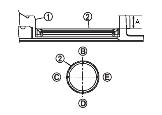
7. Install new front oil seal to front cover. Refer to Removal and Installation.Removal and Installation

8. Install front cover with the following procedure:
(1) Install tension guide (upper) to front cover.
(2) If removed, install the camshaft sprocket (INT) oil seal.
| caution | Do not reuse camshaft sprocket (INT) oil seal if removed from front cover. |
(3) Install new O-rings and filter.
| caution | Do not reuse O-rings or filter. |
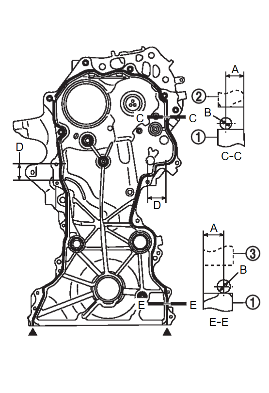
(4) Apply a continuous bead of liquid gasket with a suitable tool to front cover  as shown.
 as shown.
 | : Cylinder head |
 | : Ladder assembly |
| A | : 4.0 - 5.6 mm (0.16 - 0.22 in) |
| B | : φ 2.7 – 3.7 mm (0.11 – 0.15 in) |
| C | : Cylinder head and cylinder block mating surface |
| D | : φ 6.0 – 7.0 mm (0.24 – 0.28 in) |
| E | : Ladder assembly mating surface |
Use Genuine RTV Silicone Sealant or an equivalent. Refer to Recommended Chemical Products and SealantsRecommended Chemical Products and Sealants .
.
 .
.| caution |
|
(5) Make sure the mating marks on the timing chain and each sprocket are still aligned. Then install the front cover.
| caution | Do not damage the front oil seal or camshaft sprocket (INT) oil seal during installation. |
9. Install crankshaft pulley using the following procedure:
(1) When inserting crankshaft pulley with a suitable tool, tap on its center portion (not circumference).
| caution | Do not damage front oil seal lip portion. |
(3) Apply new engine oil to thread and seat surfaces of crankshaft pulley bolt.
(4) Tighten crankshaft pulley bolt to the specified torque.
| Crankshaft bolt | : 42.1 N·m (4.3 kg-m, 31 ft-lb) |
(5) Tighten crankshaft pulley bolt to the specified angle using angle wrench [SST: KV10112100 (BT-8653-A)].
| caution | Check and confirm the tightening angle using angle wrench [SST: KV10112100 (BT-8653-A)]. Avoid judgment by visual inspection without Tool. |
| Tightening angle | : 90° - 96° |
(6) Check that crankshaft rotates clockwise smoothly.
10. Install the electric intake valve timing control actuator and tighten the bolts to the specified torque in the sequence shown.
11. Installation of the remaining components is in the reverse order of removal.
- Perform "Electric intake valve timing control actuator position learning". Refer to Work Procedure.Work Procedure

- Perform the “Throttle Valve Closed Position Learning” when harness connector of electric throttle control actuator is disconnected. Refer to Work Procedure.Work Procedure

![[Previous]](../../../buttons/fprev.png)
![[Next]](../../../buttons/fnext.png)

 ) shown.