Removal and Installation
REMOVAL
| warning | To avoid the danger of being scalded, do not drain the coolant when the engine is hot. |
| note | When removing components such as hoses, tubes/lines, etc., cap or plug openings to prevent fluid from spilling. |
1. Disconnect battery negative terminal.
2. Remove the air cleaner case assembly and air duct. Refer to Removal and Installation .
.
 .
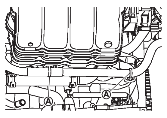
.3. Partially drain engine coolant. Refer to Draining .
.
 .
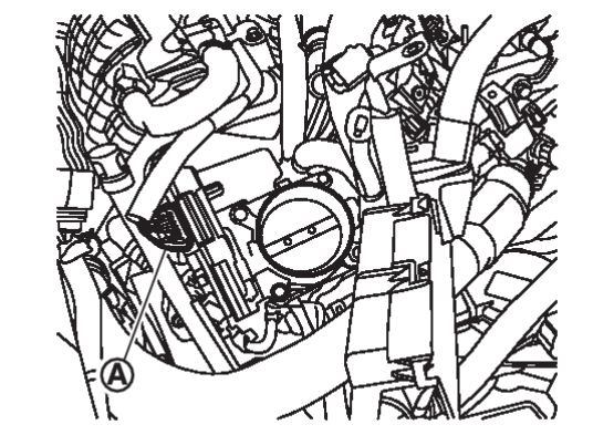
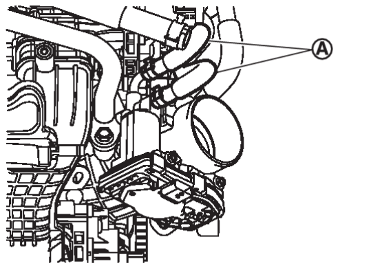
.5. Disconnect water hoses  from the electric throttle control actuator.
 from the electric throttle control actuator.
| note | When removing only intake manifold, position electric throttle control actuator aside without disconnecting the water hose. |
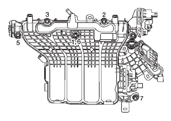
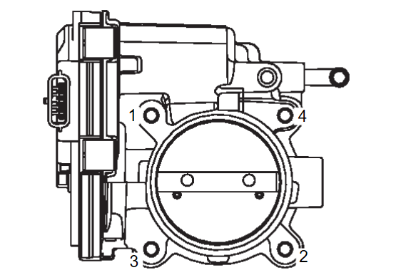
6. Loosen bolts in reverse order as shown, then remove electric throttle control actuator and electric throttle actuator gasket.
| caution | Handle carefully to avoid any damage. |
9. Remove CVT fluid charging pipe. Refer to Exploded View.Exploded View

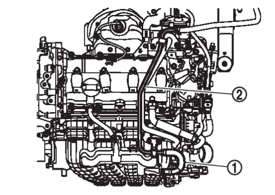
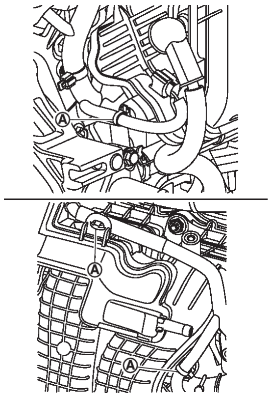
10. Disconnect the PCV hose from the intake manifold assembly.
11. Disconnect the EVAP canister purge volume control solenoid valve hose 1 from the intake manifold assembly.
12. Disconnect harness connectors from the intake manifold runner control valve motor, intake manifold runner control valve position sensor, intake manifold tuning valve motor and manifold absolute pressure (MAP) sensor.
14. Loosen nuts and bolts in reverse of the sequence shown and remove the intake manifold.
| caution |
|
| note |
15. Remove intake port insulator.
| caution | Do not reuse intake port insulator gasket. |
16. Remove the intake manifold stud if necessary.
INSTALLATION
Installation is in the reverse order of removal.
- Add engine coolant if necessary. Refer to Refilling
 .
. - Perform the “Throttle Valve Closed Position Learning” when harness connector of electric throttle control actuator is disconnected. Refer to Work Procedure
 .
. - Perform the “Idle Air Volume Learning” and “Throttle Valve Closed Position Learning” when electric throttle control actuator is replaced. Refer to Work Procedure
 (Idle Air Volume Learning) and Work Procedure
 (Throttle Valve Closed Position Learning).
Intake Manifold
1. Install the intake manifold stud if removed.
2. Install intake port insulator.
| caution | Do not reuse intake port insulator gasket. |
3. Securely install intake manifold gasket to the mounting groove.
| caution | Do not reuse intake manifold gasket. |
4. Install and tighten intake manifold nuts and bolts using the following procedure:
| caution | Do not reuse intake manifold gasket. |
(2) Tighten intake manifold nuts and bolts to the specified torque in the sequence shown.
 1, 4, 5, 6 1, 4, 5, 6 | : 25.0 N·m (2.6 kg-m, 18 ft-lb) |
 2, 3 2, 3 | : 25.0 N·m (2.6 kg-m, 18 ft-lb) |
 7 7 | : 25.0 N·m (2.6 kg-m, 18 ft-lb) |
6. Installation is in the reverse order of removal.
![[Previous]](../../../buttons/fprev.png)
![[Next]](../../../buttons/fnext.png)
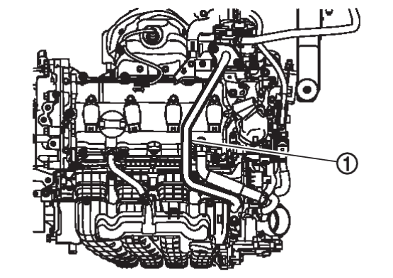
 and brake booster vacuum tube
  from the intake manifold.