Removal and Installation
| warning |
|
REMOVAL
1. Release the fuel pressure. Refer to Work ProcedureWork Flow .
.
 .
.2. Disconnect the battery negative terminal. Refer to Removal and Installation .
.
 .
.3. Remove intake manifold. Refer to Removal and Installation .
.
 .
.4. Remove high pressure fuel rail protector.
5. Remove high pressure fuel rail insulator.
6. Remove high pressure fuel tube. Refer to Removal and Installation.Removal and Installation

7. Disconnect harness connector from fuel rail pressure sensor.
8. Disconnect harness connector from fuel injector.
9. Remove fuel rail pressure sensor if necessary.
10. Remove high pressure fuel rail and fuel injector assembly.
| caution |
|
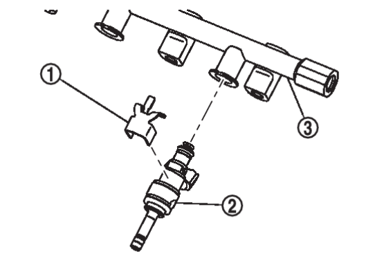
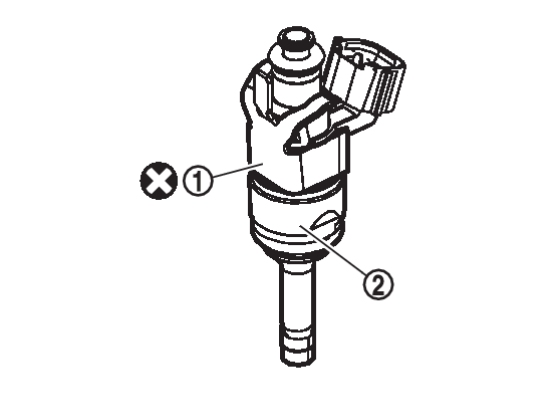
11. Remove fuel injector from high pressure fuel rail with the following procedure:
- Remove fuel injector
 from high pressure fuel rail
  by pulling straight.
caution - Be careful with remaining fuel that may go out from fuel tube.
- Be careful not to damage fuel injector nozzle during removal.
- Never bump or drop fuel injector.
- Never disassemble fuel injector.
- Open and remove clip
 if necessary.
 - Remove O-ring, backup ring and injector holder from direct fuel injector.
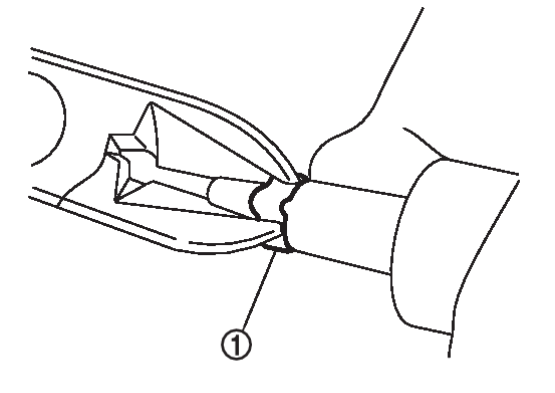
caution Do not reuse O-ring, backup ring or injector holder. - Cut seal ring
 while pinching it.
caution - Do not scratch direct fuel injector when removing seal ring.
- Do not reuse seal ring.
12. Remove the high pressure fuel rail studs from the cylinder head if necessary.
INSTALLATION
1. If removed, install the high pressure fuel rail studs.
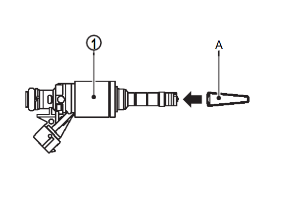
2. Install seal ring to fuel injector using the following procedure:
| caution |
|
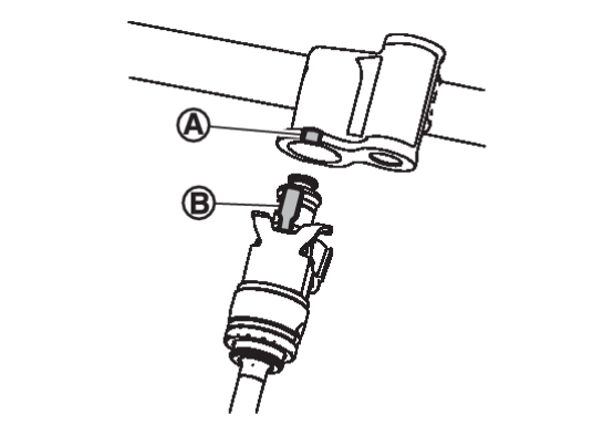
- Install seal guide [SST:KV10119720 (J-50364)] (A) to fuel injector
 .
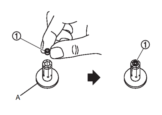
. - Set seal ring
 into seal installer [SST:KV10119730 (J-50364)] (A).
 - Straightly insert seal ring
 , which is set in step b, to fuel injector as shown and install onto fuel injector.
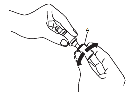
caution Be careful that seal ring does not exceed the groove portion of fuel injector. - Insert drift [SST:KV10119710 (J-50364)] (A) to fuel injector and rotate clockwise and counterclockwise by 90° while pressing seal ring to fit it.
note This is done to correct any elongation of the seal ring caused by installation and for preventing sticking when inserting fuel injector into cylinder head.
3. Install O-ring and backup ring to fuel injector.
| caution |
|
4. Install the fuel injectors and high pressure fuel rail using the following procedure:
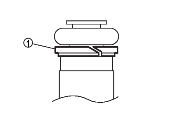
- Install the injector holder
 onto the fuel injector
  .
.caution - Do not reuse injector holder.
- Be careful to keep injector holder from interfering with O-ring. If interference occurs, replace O-ring.
- Insert fuel injector into high pressure fuel rail with injector holder attached.
- Check that installation is complete by checking that fuel injector does not rotate or come off.
- Check that tabs of injector holders and high pressure fuel rail are aligned after installation.
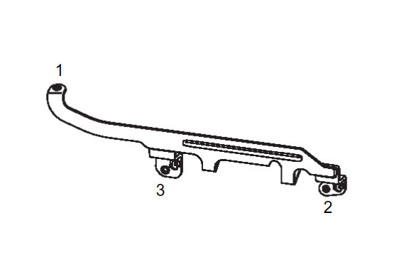
5. Install the fuel injector and high pressure fuel rail assembly into the cylinder head and tighten the nuts and bolts using the following procedure:
- Temporarily tighten mounting fuel rail bolt 2 and fuel rail nut 3.
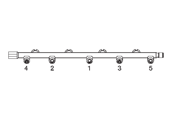
- Tighten mounting fuel rail nuts and bolts to the specified torque in the sequence shown.
High pressure fuel rail nuts and bolts 
: 10.0 N·m (1.0 kg-m, 89 in-lb) - Tighten nuts and bolts to the specified torque in the sequence shown.
High pressure fuel rail nuts and bolts 
: 20.5 N·m (2.1 kg-m, 15 ft-lb)
6. Install the fuel rail pressure sensor if necessary using the following procedure:
| caution |
|
- Lubricate fuel rail pressure sensor threads with clean engine oil.
caution Check that high pressure fuel rail and fuel rail pressure sensor threads have no damage or foreign matter. - Tighten fuel rail pressure sensor to the specified torque.
Fuel rail pressure sensor 
: 10.0 N·m (1.0 kg-m, 89 in-lb) - Tighten fuel rail pressure sensor to the specified angle using angle wrench [SST:KV10112100 (BT-8653-A)].
caution - To check tightening angle, use Tool. Do not judge the angle by visual inspection.
- The torque value for the angle tightening must be 90 N·m (9.2 kg-m, 66 ft-lb) or less.
- If torque value reaches 90 N·m (9.2 kg-m, 66 ft-lb), then replace the fuel rail pressure sensor and high pressure fuel rail with a new one.
Tightening angle : 45°
7. Connect the fuel rail pressure sensor harness connector.
8. Connect the fuel injector harness connector.
9. Install the high pressure fuel tube. Refer to Removal and Installation.Removal and Installation

10. Install the high pressure fuel rail protector using the following procedure:
11. Installation of the remaining components is in the reverse order of removal.
![[Previous]](../../../buttons/fprev.png)
![[Next]](../../../buttons/fnext.png)

 of injector holder is aligned to cutout
  of high pressure fuel rail.