DTC P105B: Electrical oil pump stuck-ON
MONITOR EXECUTION
- Continuous
MONITOR EXECUTION CONDITIONS (Other monitor and Sensor)
Other Monitor (There is no temporary DTC stored in memory for the item monitored below)
- Not applicable
Sensor (The sensor below is determined to be normal)
- Not applicable
DTC SET CONDITIONS
Check Conditions
- Power drive unit (GCU) power supply voltage is 8 volts to 16 volts.
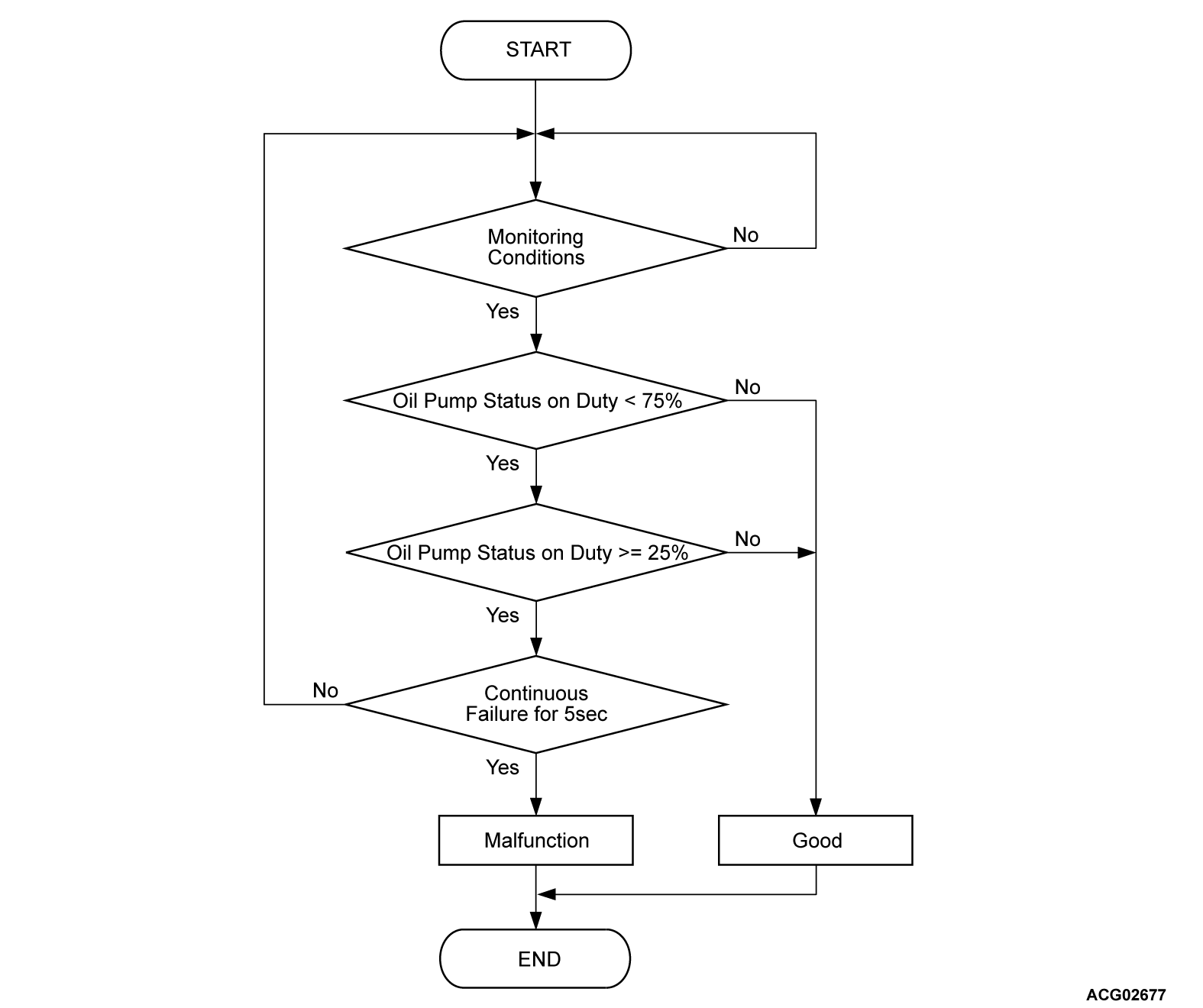
- Oil pump drive duty command is 10 % (Stop).
Judgment Criterion
- Change of the oil pump duty status is 25 % to 75 % for 5 seconds.
PROBABLE CAUSES
- Damaged harness wires and connectors
- Noise interruption in signal wires
- Oil filter clogging
- Pipe clogging
- Malfunction of the oil pump
- Malfunction of the power drive unit [generator control unit (GCU)]
DIAGNOSIS
Required Special Tools
- MB991223: Wiring harness set
- MB992006: Extra fine probe
STEP 1. Measure the resistance in the OPMP line between the electric oil pump connector and the power drive unit connector.
(1) Disconnect the electric oil pump connector and power drive unit connector.
(2) Measure the resistance between the electric oil pump connector and the power drive unit connector (OPMP terminal).
OK: Continuity exists (2 Ω or less)
Is the check result normal?
STEP 2. Using scan tool (M.U.T.-IIISE), check whether the DTC is set.
Check whether the power drive unit [generator control unit (GCU)] set a DTC P105C or P10AE which is related to the electric oil pump.
Is the DTC set?
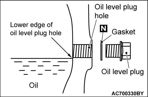
STEP 3. Check the oil level.
Check that the oil level is at the lower edge of the oil level plug hole.
Is the check result normal?
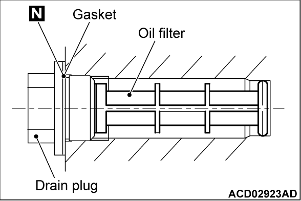
STEP 4. Oil filter check
Remove the generator drain plug, check that the oil filter behind it is not clogged or damaged. Replace the oil filter and the oil (Refer to GROUP 14B - On-Vehicle Service <Oil Cooling System> - Oil Change
  ). Then go to Step 6
 .
. Replace the EV oil cooler (Refer to GROUP 14B - EV Oil Cooler
  ), EV oil cooler hose and EV oil cooler pipe (Refer to GROUP 14B - Oil Hose and Pipe
  ), the EV oil cooler bypass valve and electric oil pump (Refer to GROUP 14B - Electric Oil Pump/EV Oil Cooler Bypass Valve
  ), the oil filter and the oil (Refer to GROUP 14B - On-Vehicle Service <Oil Cooling System> - Oil Change
  ). Then go to Step 6
 .
.
Is the check result normal?
 Replace the oil filter and the oil (Refer to GROUP 14B - On-Vehicle Service <Oil Cooling System> - Oil Change
  ). Then go to Step 6
 .
. Replace the EV oil cooler (Refer to GROUP 14B - EV Oil Cooler
  ), EV oil cooler hose and EV oil cooler pipe (Refer to GROUP 14B - Oil Hose and Pipe
  ), the EV oil cooler bypass valve and electric oil pump (Refer to GROUP 14B - Electric Oil Pump/EV Oil Cooler Bypass Valve
  ), the oil filter and the oil (Refer to GROUP 14B - On-Vehicle Service <Oil Cooling System> - Oil Change
  ). Then go to Step 6
 .
.STEP 5. Using scan tool (M.U.T.-IIISE), check the actuator test.
| caution | When ambient temperature is -15°C (5°F) or less, the oil pump may not operate stably. Execute the actuator test only when the temperature is above -15°C (5°F). |
(2) Check for the existence of oil leakage.
Is the oil level appropriate?
![[Previous]](../../../buttons/fprev.png)
![[Next]](../../../buttons/fnext.png)


