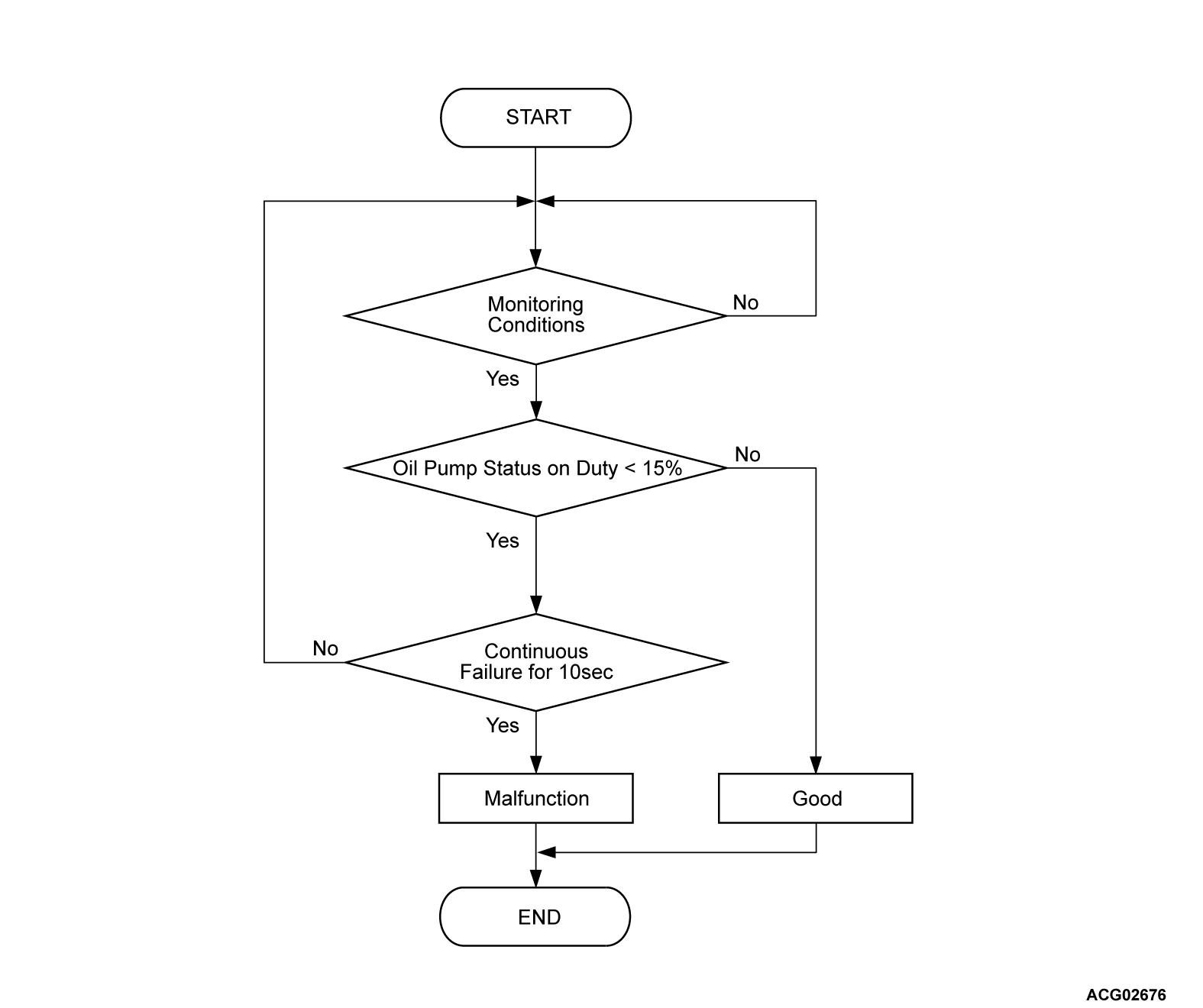
DTC P10AE: Electrical oil pump stuck-OFF2
MONITOR EXECUTION
- Continuous
MONITOR EXECUTION CONDITIONS (Other monitor and Sensor)
Other Monitor (There is no temporary DTC stored in memory for the item monitored below)
- Not applicable
Sensor (The sensor below is determined to be normal)
- Not applicable
DTC SET CONDITIONS
Check Conditions
- Power drive unit (GCU) power supply voltage is 8 volts to 16 volts.
- Oil pump drive duty command is more than 15 % (Active).
Judgment Criterion
- Change of the oil pump duty status is less than 15 % for 10 seconds.
PROBABLE CAUSES
- Electric oil pump circuit system fails
- Oil cooling system fails
- Malfunction of the water/oil pump relay
- Malfunction of the PHEV-ECU
- Malfunction of the electric oil pump
- Malfunction of the generator
- Damaged wiring harness
DIAGNOSIS
Required Special Tools
- MB991223: Wiring harness set
- MB992006: Extra fine probe
STEP 1. Using scan tool (M.U.T.-IIISE), check whether the other DTC is set.
Check whether the PHEV-ECU sets a power supply-related DTC P0C73.
Is the DTC set?
STEP 2. Water/oil pump relay check
STEP 3. Measure the resistance in the 12V starter battery line between the 12V starter battery positive terminal and the water/oil pump relay connector.
(1) Disconnect the 12V starter battery positive terminal.
(2) Remove the water/oil pump relay.
(3) Measure the resistance between the 12V starter battery positive terminal and the relay box 3 (water/oil pump relay connector).
OK: Continuity exists (2 Ω or less)
Is the check result normal?
STEP 4. Measure the resistance in the WPR- line between the PHEV-ECU connector and the water/oil pump relay connector.
(1) Disconnect the PHEV-ECU connector.
(2) Remove the water/oil pump relay.
(3) Measure the resistance between the PHEV-ECU connector (WPR- terminal) and the relay box 3 (water/oil pump relay connector).
OK: Continuity exists (2 Ω or less)
Is the check result normal?
STEP 5. Measure the resistance in the power supply line between the electric oil pump connector and the water/oil pump relay connector.
(1) Disconnect the electric oil pump connector.
(2) Remove the water/oil pump relay.
(3) Measure the resistance between the electric oil pump connector (power supply terminal) and the relay box 3 (water/oil pump relay connector).
OK: Continuity exists (2 Ω or less)
Is the check result normal?
STEP 6. Measure the resistance in the OPCP line between the electric oil pump connector and the power drive unit connector.
(1) Disconnect the electric oil pump connector and power drive unit connector.
(2) Measure the resistance between the electric oil pump connector and the power drive unit connector (OPCP terminal).
OK: Continuity exists (2 Ω or less)
Is the check result normal?
![[Previous]](../../../buttons/fprev.png)
![[Next]](../../../buttons/fnext.png)


