System Description
DESCRIPTION
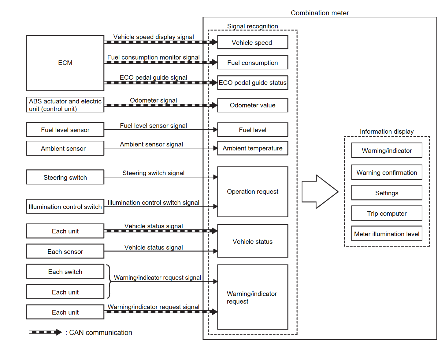
- The combination meter receives signals necessary for controlling the operation of the information display from each unit, sensor and switch.
- The combination meter incorporates a trip computer that displays the warning/information according to the information received from each unit, sensor and switch.
- The combination meter shows the following functions on the information display.
- Warning/Indicator
- Warning confirmation
- Setting
- Trip computer
- Personal display
- Meter illumination level
- The items that displayed to information display can be selected by the steering switch, and illumination control switch. For further details, Refer to Steering Switch
 or Illumination Control Switch
 .
.
WARNING/INDICATOR LIST
WARNING
| Warning | Reference |
| Headlight warning | Refer to Headlight WarningHeadlamp Warning . . |
| Light reminder warning | Refer to Light Reminder Warning (Information Display) . . |
| Washer fluid warning | Refer to Washer fluid warningWasher Fluid Warning . . |
| AWD warning | Refer to AWD Warning . . |
| Door open warning | Refer to Door Open Warning . . |
| Keyless operation key low battery warning | Refer to Keyless operation key Low Battery WarningIntelligent Key Low Battery Warning . . |
| Keyless operation key system malfunction | Refer to Keyless operation key System MalfunctionIntelligent Key System Malfunction . . |
| Take away warning | Refer to Take Away Warning (Information Display)Take Away Warning . . |
| Parking sensor error | Refer to Parking Sensor Error . . |
| Chassis control warning | Refer to Chassis control warningChassis Control Warning . . |
| Parking brake warning | Refer to Parking Brake Warning . . |
| Automatic brake hold warning | Refer to Automatic Brake Hold Warning . . |
| Low tire pressure warning | Refer to Low Tire Pressure Warning . . |
| Low fuel warning | Refer to Low fuel warning . . |
| Engine warning | Refer to Indicator/InformationWarning/Indicator (On Information Display) . . |
| Electric shift warning | Refer to Electric Shift Warning . . |
| CVT system warning | Refer to CVT System Warning . . |
INDICATOR
| Indicator | Reference |
| Shift position indicator | Refer to Shift Position Indicator . . |
| Neutral hold mode indicator | Refer to Neutral Hold Mode Indicator . . |
| Remote engine start information | Refer to Remote Engine Start Information . . |
| AWD torque distribution indicator | Refer to AWD Torque Distribution Indicator . . |
| Engine start information | Refer to Engine Start Information . . |
| Key ID verification information | Refer to Key ID Verification Information . . |
| Audio indicator | Refer to Meter Display Function . . |
| Hands-free phone indicator | Refer to Meter Display Function . . |
| Sonar indicator | Refer to Sonar Indicator . . |
| Driving position memory | Refer to Driving Position Memory . . |
| Tire pressure display | Refer to Tire Pressure Display . . |
| Drive mode indicator | Refer to Drive Mode Indicator . . |
| ASCD indicator | Refer to Indicator/InformationWarning/Indicator (On Information Display) . . |
| Oil control system (OCS) indicator | Refer to Indicator/InformationWarning/Indicator (On Information Display) . . |
| Alert | Refer to AlertAlert . . |
| Maintenance | Refer to Maintenance . . |
| Low outside temperature display | Refer to Low outside temperature display . . |
WARNING CONFIRMATION
- The combination meter can cause an interrupt on the information display to indicate a warning, based on signals received from each unit and switch.
- The indicated warning can be checked with “WARNING” during the satisfaction of an interrupt indication condition for each warning.
SETTINGS
The condition of following items can be set.
- ASC Setting
- Driver Assistance
- Personal Display
- Head-Up Display
- ECO Mode Setting
- TPMS Setting
- Clock
- Vehicle Settings
- Maintenance
- Customize Display
- Unit/Language
- Factory Reset
TRIP COMPUTER
Current Fuel Consumption
The combination meter calculates current fuel consumption based on the following signals, and the calculated value is displayed on the information display.
Current fuel consumption can be compared with average fuel consumption.
| Signal name | Signal source |
| Ignition signal | — |
| Fuel consumption monitor signal | ECM  Combination meter Combination meter |
| Vehicle speed display signal | ECM  Combination meter Combination meter |
| note |
|
Average Fuel Consumption
The combination meter calculates average fuel consumption based on the following signals, and the calculated value is displayed on the information display.
| Signal name | Signal source |
| Ignition signal | — |
| Fuel consumption monitor signal | ECM  Combination meter Combination meter |
| Vehicle speed display signal | ECM  Combination meter Combination meter |
| note |
|
Current Vehicle Speed
The combination meter calculates current vehicle speed based on the following signals, and the calculated value is displayed on the information display.
| Signal name | Signal path |
| Ignition signal | — |
| Vehicle speed display signal | ECM  Combination meter Combination meter |
| note | Current vehicle speed on the information display is updated approximately every 0.3 seconds. |
Average Vehicle Speed
The combination meter calculates average vehicle speed based on the following signals, and the calculated value is displayed on the information display.
| Signal name | Signal source |
| Ignition signal | — |
| Vehicle speed display signal | ECM  Combination meter Combination meter |
| note |
|
Travel Time
The combination meter measures and displays travel time (ignition switch ON time).
Travel Distance
The combination meter measures and displays travel distance.
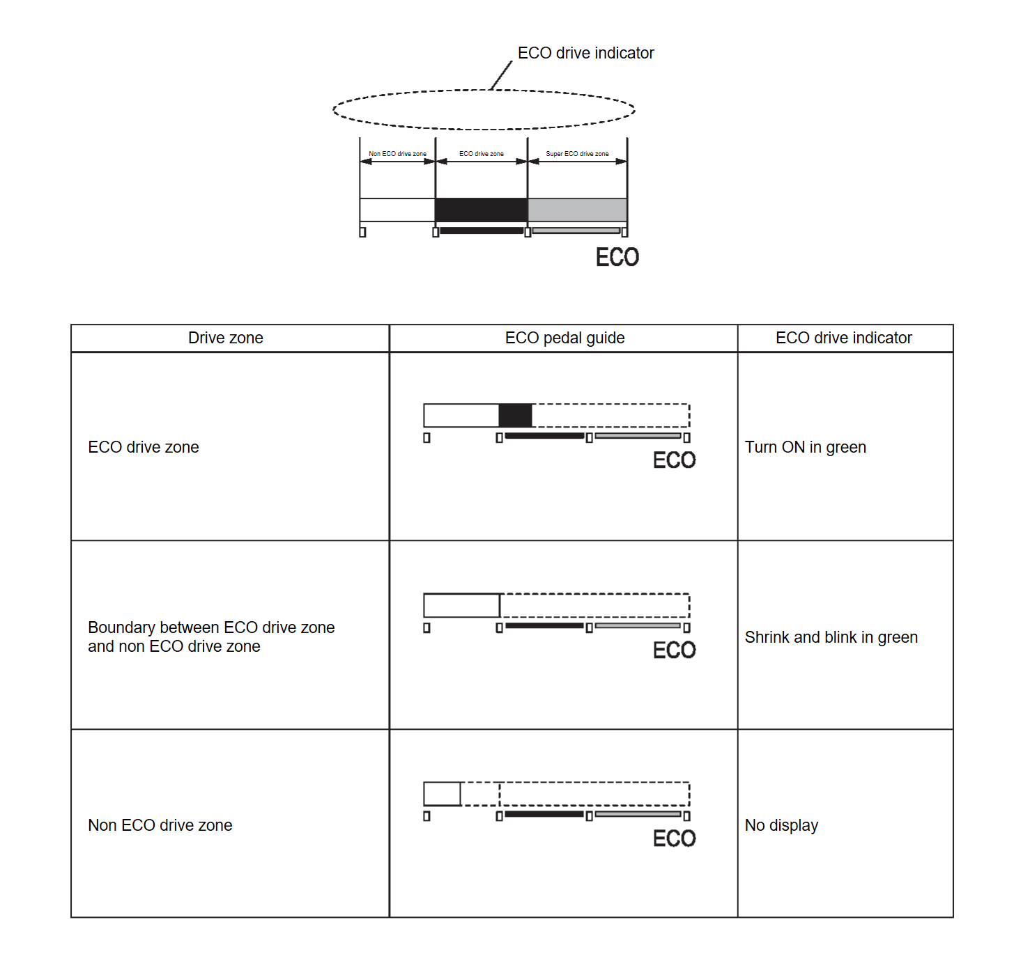
ECO Pedal Guide
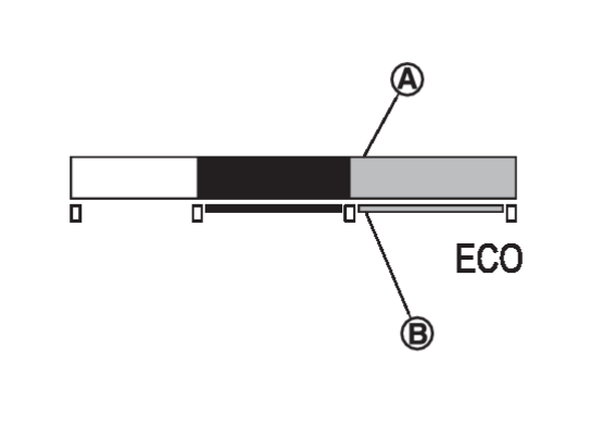
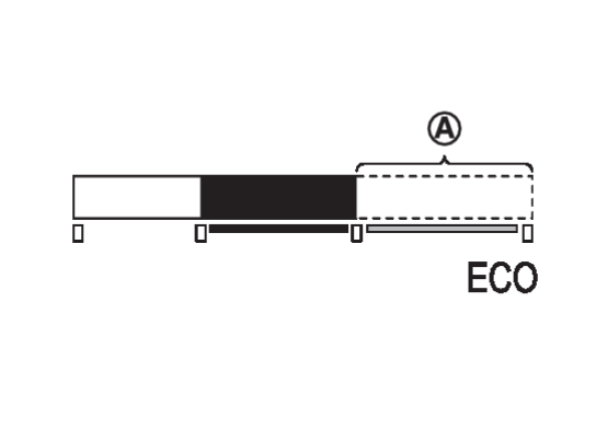
The ECO pedal guide consists of Gauge 1  (displays accelerator pedal angle) and Gauge 2
  (displays the guideline of ECO driving).
 (displays accelerator pedal angle) and Gauge 2
  (displays the guideline of ECO driving).
GAUGE1
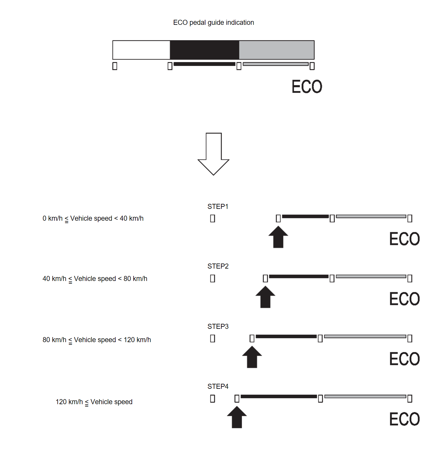
- ECM corrects the accelerator pedal angle to the maximum angle for ECO driving, according to vehicle speeds.The maximum accelerator pedal angle increases/decreases as the vehicle speed increases/decrease.The maximum accelerator angle corrected by ECM is the limitation of ECO driving. The ECO driving is possible only when the number of unlit segments
 of the indicator bar is equal to or less than that of Gauge 2.The less the number of unlit segments
 of the indicator bar, the more the degree of ECO driving is. And the more the number of unlit segments, the less the degree of ECO driving is.ECM judges the number of lighting segments according to the accelerator pedal angle and vehicle speed and transmits a CAN communication signal to the combination meter via CAN communication.The combination meter indicates the number of segments necessary for the ECO pedal guide, according to an ECO pedal guide signal.
note The combination meter corrects the number of lighting segments according to a vehicle speed signal.
GAUGE2
- The combination meter turns ON/OFF the Gauge 2 (guide line for ECO driving) according to a vehicle speed signal.
ECO DRIVE INDICATOR
| Signal name | Signal path | |
| Ignition signal | — | |
| ECO pedal guide signal | ECM  Combination meter Combination meter | |
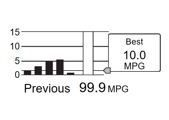
ECO Drive Report
- The ECO drive report is a function which displays the last five data of average fuel consumption, present fuel economy (present value), and the best fuel economy (highest value) on the information display by calculating and recording average fuel consumption.
- The combination meter calculates the average fuel consumption according to the signal below, detects the status of ECO mode , and displays “ECO drive report” on the information display when the ignition switch is turned ON→OFF.
Signal name Signal path Ignition signal — Fuel consumption monitor signal ECM  Combination meter
Vehicle speed display signal ECM  Combination meter
ECO mode indicator signal ECM  Combination meter
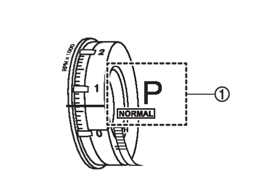
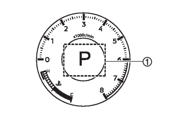
PERSONAL DISPLAY
The combination meter can displays the various information on personal display  .
.
 .
.The information displayed on the personal display can be selected by the combination meter setting menu.
METER ILLUMINATION LEVEL
The combination meter displays the illuminance level of the back light on the information display by turning the illumination control switch.
Refer to System DescriptionSystem Description .
.
 .
.![[Previous]](../../../buttons/fprev.png)
![[Next]](../../../buttons/fnext.png)
