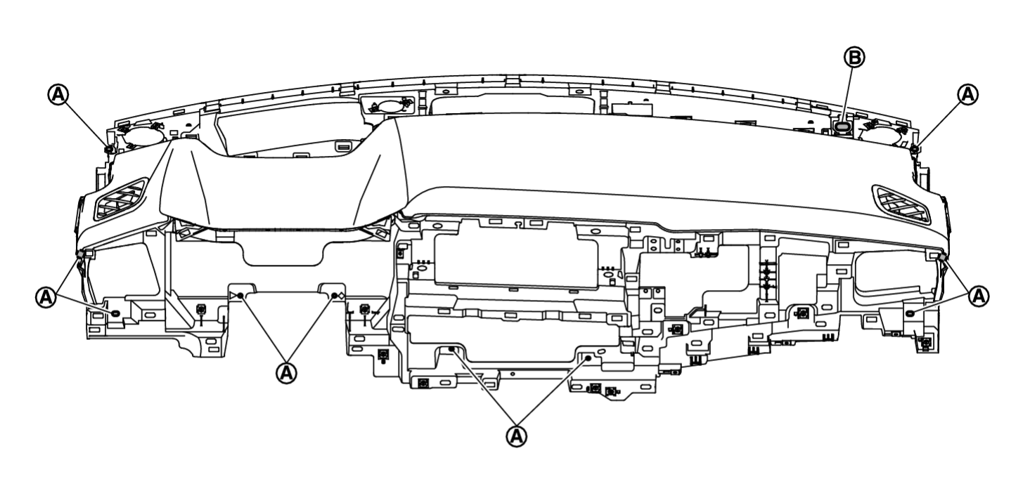
Removal and Installation
WORK STEP
When removing instrument panel assembly, combination meter and AV control unit take steps in the order shown by the numbers below.
| PARTS | INSTRUMENT PANEL ASSEMBLY | COMBINATION METER | AV CONTROL UNIT |
| Center console assembly | [1] | ||
| Instrument mask RH | [2] | ||
| Glove box | [3] | ||
| Passenger knee air bag module | [4] | ||
| Instrument mask LH | [5] | ||
| Fuse block lid | [6] | ||
| Instrument lower panel LH | [7] | ||
| Driver knee air bag module | [8] | ||
| Switch panel | [9] | ||
| Mood light (instrument panel center) [with mood light (instrument panel center)] | [10] | ||
| Light mask [without mood light (instrument panel center)] | [11] | ||
| Instrument lower panel center | [12] | ||
| Driver air bag module | [13] | ||
| Steering wheel | [14] | ||
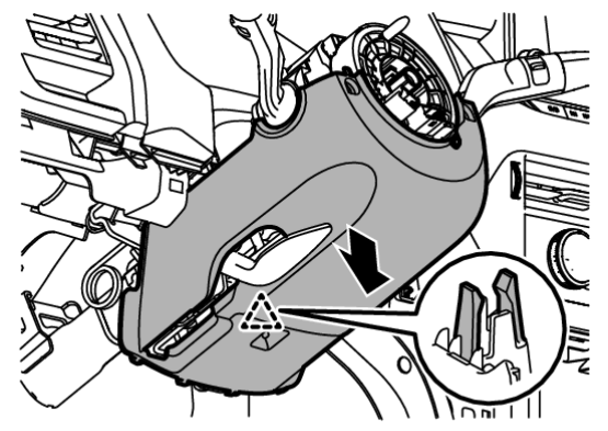
| Steering column cover | [15] | ||
| Spiral cable | [16] | ||
| Steering angle sensor | [17] | ||
| Combination switch | [18] | ||
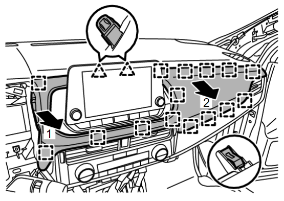
| Cluster lid A | [19] | [1] | [1] |
| Combination meter | [20] | [2] | |
| Instrument pad A | [21] | ||
| Instrument pad B | [22] | [2] | |
| AV control unit | [23] | [3] | |
| Center ventilator finisher and A/C switch assembly | [24] | ||
| Intelligent key unit | [25] | ||
| Side ventilator grille assembly RH | [26] | ||
| Front pillar garnish (LH and RH) | [27] | ||
| Speaker grille LH | [28] | ||
| Speaker grille RH | [29] | ||
| Instrument panel speaker | [30] | ||
| Optical sensor | [31] | ||
| Sunload sensor (automatic air conditioner) | [32] | ||
| Instrument garnish | [33] | ||
| Meter speaker | [34] | ||
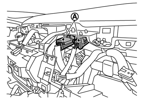
| Passenger air bag module harness connector | [35] | ||
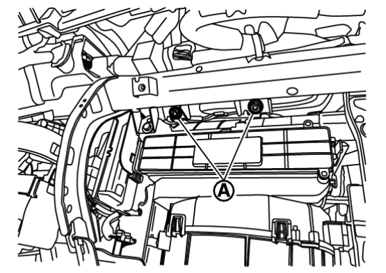
| Passenger air bag module mounting bolt | [36] | ||
| Instrument panel assembly | [37] |
[]: Number indicates step in removal procedure.
REMOVAL
| warning | Before servicing, ignition switch OFF, disconnect battery negative terminal and wait for 3 minutes or more. |
| caution |
|
1. Remove center console assembly. Refer to Removal and Installation .
.
 .
.2. Remove instrument mask RH.
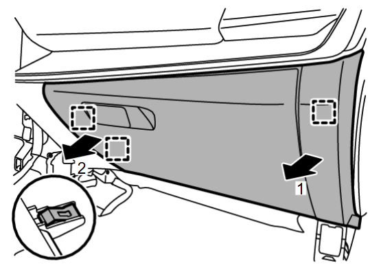
3. Remove glove box.
(2) Disengage fixing metal clips according to numerical order 1→2 indicated by arrows as shown in the figure, and then remove glove box.
 | : Metal clip |
(3) Disconnect harness connector (if equipped).
4. Remove passenger knee air bag module. Refer to Removal and Installation .
.
 .
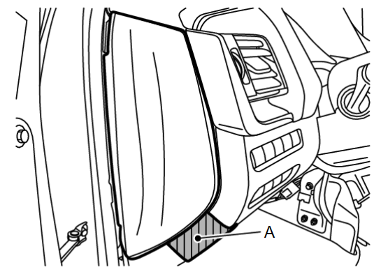
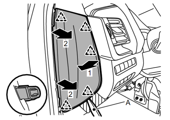
.5. Remove instrument mask LH.
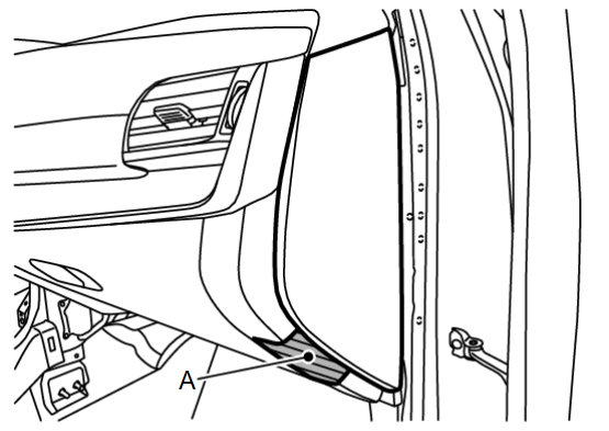
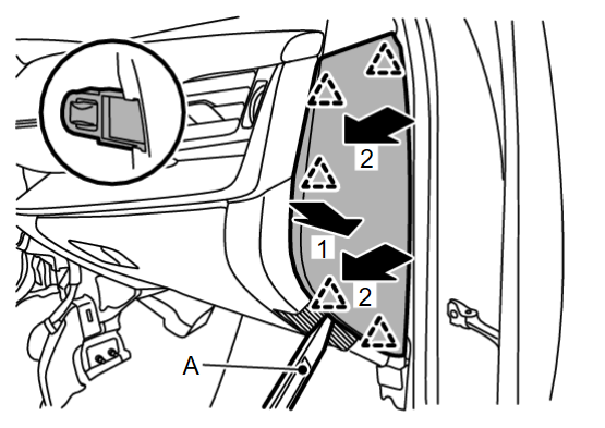
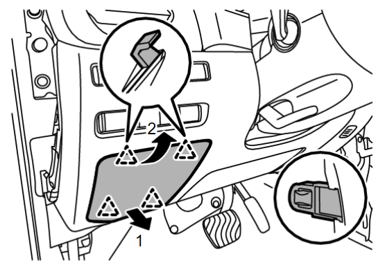
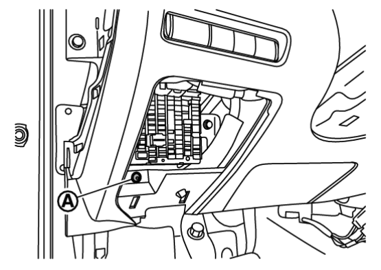
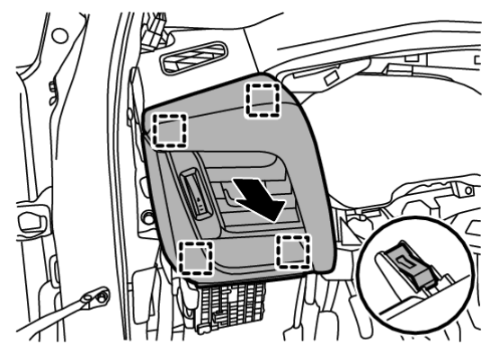
6. Disengage fixing pawls according to numerical order 1→2 indicated by arrows as shown in the figure, and then remove fuse block lid.
 | : Pawl |
7. Remove instrument lower panel LH.
(2) Disengage fixing pawls and metal clips according to numerical order 1→2 indicated by arrows as shown in the figure, and then pull out instrument lower panel LH.
 | : Pawl |
 | : Metal clip |
(3) Disconnect harness connectors, harness clips and data link connector, and then remove instrument lower panel LH.
8. Remove driver knee air bag module. Refer to Removal and Installation .
.
 .
.9. Remove switch panel.
(3) Disconnect harness connectors, and then remove switch panel.
10. Remove mood light (instrument panel center) [with mood light (instrument panel center)]. Refer to Removal & Installation .
.
 .
.11. Remove light mask [without mood light (instrument panel center)].
12. Remove instrument lower panel center.
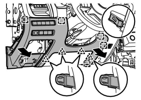
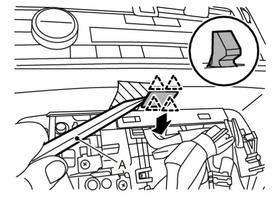
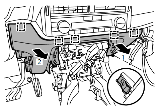
(2) Disengage fixing metal clips according to numerical order 1→2 indicated by arrows as shown in the figure, and then pull out instrument lower cover center.
 | : Metal clip |
(3) Disconnect harness connector and aspirator duct (if equipped), and then remove instrument lower cover center.
13. Remove driver air bag module. Refer to Removal and Installation .
.
 .
.14. Remove steering wheel. Refer to Removal and Installation .
.
 .
.15. Remove steering column cover.
16. Remove spiral cable. Refer to Removal and Installation .
.
 .
.17. Remove steering angle sensor. Refer to Removal and Installation .
.
 .
.18. Remove combination switch. Refer to Removal and Installation .
.
 .
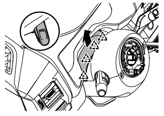
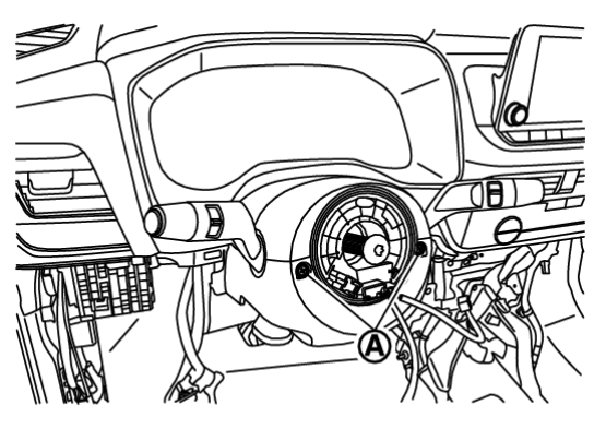
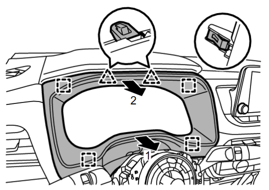
.19. Disengage fixing pawls and metal clips according to numerical order 1→2 indicated by arrows as shown in the figure, and then remove cluster lid A.
 | : Pawl |
 | : Metal clip |
| note | When only removing the combination meter and AV control unit, float the instrument lower panel center and instrument lower panel LH to secure a space, and then remove the cluster lid A. |
20. Remove combination meter. Refer to the following.
- With full TFT meter : Refer to Removal and Installation
 .
. - With 7 inch information display : Refer to Removal and Installation
 .
.
21. Remove instrument pad A.
(1) Disengage fixing metal clips, and then remove instrument pad A and side ventilator grille assembly LH as an assembly.
 | : Metal clip |
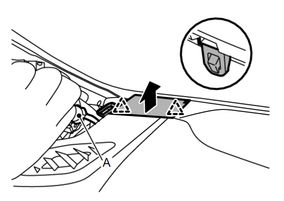
22. Remove instrument pad B.
23. Remove AV control unit. Refer to Removal and Installation .
.
 .
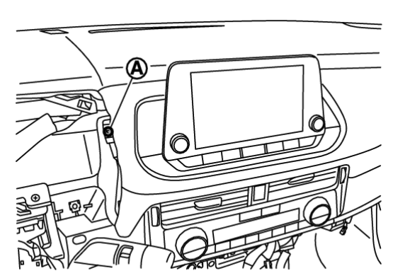
.24. Remove center ventilator finisher and A/C switch assembly.
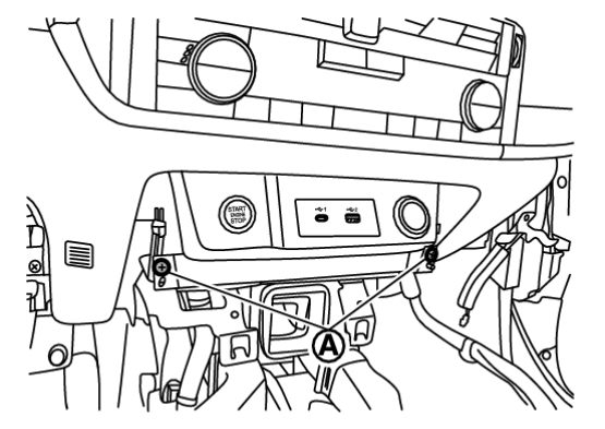
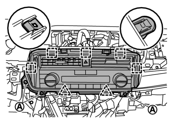
(1) Remove fixing screws  .
.
 .
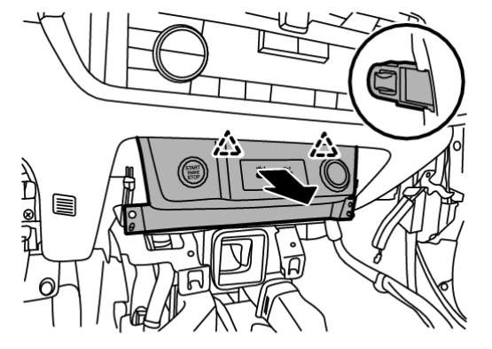
.(2) Disengage fixing pawls and metal clips, and then pull out center ventilator finisher and A/C switch assembly as an assembly.
 | : Pawl |
 | : Metal clip |
(3) Disconnect harness connectors, and then remove center ventilator finisher and A/C switch assembly as an assembly.
25. Remove intelligent key unit. Refer to Removal and Installation .
.
 .
.26. Remove side ventilator grille assembly RH.
27. Remove front pillar garnish (LH and RH). Refer to Removal and Installation .
.
 .
.30. Remove instrument panel speaker. Refer to the following.
- With BOSE : Refer to Removal and Installation
 .
. - Without BOSE : Refer to Removal and Installation
 .
.
31. Remove optical sensor. Refer to Removal and Installation .
.
 .
.32. Remove sunload sensor (automatic air conditioner). Refer to Removal and Installation .
.
 .
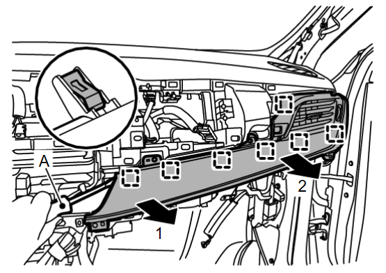
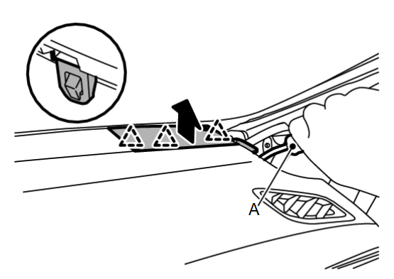
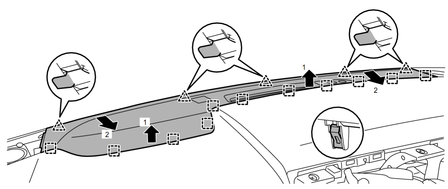
.33. Disengage fixing pawls and metal clips, and then remove instrument garnish according to numerical order 1→2 indicated by arrows as shown in the figure.
 | : Pawl |
 | : Metal clip |
34. Remove meter speaker (with 7 inch information display). Refer to Removal and Installation .
.
 .
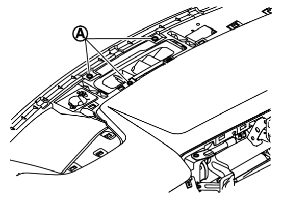
.37. Remove instrument panel assembly.
(3) Disengage harness fixing clips and disconnect harness from instrument panel assembly.
(4) Remove instrument panel assembly from passenger door opening portion.
| caution | When removing instrument panel assembly, 2 workers are required to prevent it from dropping. |
38. Remove the following parts after removing instrument panel assembly.
- Passenger air bag module : Refer to Removal and Installation
 .
. - Side defroster grille (LH and RH) : Refer to Removal and Installation
 .
. - Side defroster nozzle (LH and RH) : Refer to Removal and Installation
 .
. - Telematics antenna (with telematics system) : Refer to Removal & Installation
 .
.
INSTALLATION
Note the following items, and then install in the reverse order of removal.
| caution |
|
![[Previous]](../../../buttons/fprev.png)
![[Next]](../../../buttons/fnext.png)





 .
.