DTC P0C78: Hybrid BATT. precharge time long
| danger |
| caution | Before replacing the ECU, ensure that the communication circuit is normal. |
DESCRIPTIONS OF MONITOR METHODS
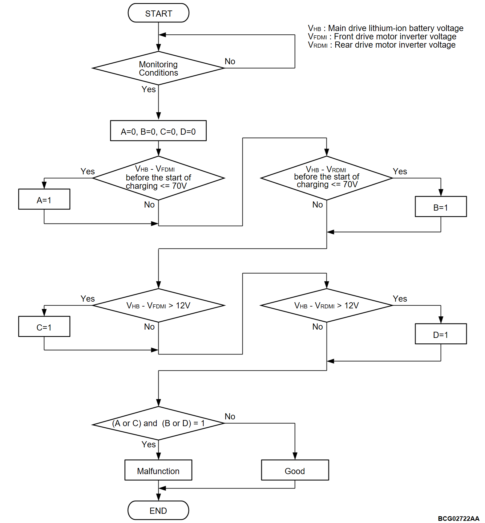
- The difference between main drive lithium-ion battery total voltage and inverter voltage is monitored to confirm front electric motor control unit (FEMCU) or rear electric motor control unit (REMCU) capacitor charge status.
- Front electric motor control unit (FEMCU) or rear electric motor control unit (REMCU) capacitor charge status is judged under the following conditions.
- Before charge: Main contactor (P) control circuit active command off.
- Before charge: Main contactor (N) control circuit active command on.
- Before charge: Charging contactor control circuit active command off.
- Charging: Main contactor (P) control circuit active command off.
- Charging: Main contactor (N) control circuit active command on.
- Charge: Charging contactor control circuit active command on.
MONITOR EXECUTION
- Continuous
MONITOR EXECUTION CONDITIONS (Other monitor and Sensor)
Other Monitor (There is no temporary DTC stored in memory for the item monitored below)
- EV-CAN monitor
- Front electric motor control unit (FEMCU) current monitor
- Front electric motor control unit (FEMCU) coil temperature monitor
- Front electric motor control unit (FEMCU) IGBT temperature monitor
- Front electric motor control unit (FEMCU) capacitor temperature monitor
- Front electric motor control unit (FEMCU) control module temperature monitor
- Front electric motor control unit (FEMCU) 3 phase circuit monitor
- Rear electric motor control unit (REMCU) current monitor
- Rear electric motor control unit (REMCU) coil temperature monitor
- Rear electric motor control unit (REMCU) IGBT temperature monitor
- Rear electric motor control unit (REMCU) capacitor temperature monitor
- Rear electric motor control unit (REMCU) control module temperature monitor
- Rear electric motor control unit (REMCU) 3 phase circuit monitor
- Front electric motor control unit (FEMCU) inverter voltage monitor
- Rear electric motor control unit (REMCU) inverter voltage monitor
- Front electric motor control unit (FEMCU) Control module circuit monitor
- Rear electric motor control unit (REMCU) control module circuit monitor
Sensor (The sensor below is determined to be normal)
- Front electric motor control unit (FEMCU) current sensor
- Front electric motor control unit (FEMCU) coil temperature sensor
- Front electric motor control unit (FEMCU) position sensor
- Front electric motor control unit (FEMCU) IGBT temperature sensor
- Front electric motor control unit (FEMCU) capacitor temperature sensor
- Front electric motor control unit (FEMCU) control module temperature sensor
- Rear electric motor control unit (REMCU) current sensor
- Rear electric motor control unit (REMCU) coil temperature sensor
- Rear electric motor control unit (REMCU) position sensor
- Rear electric motor control unit (REMCU) IGBT temperature sensor
- Rear electric motor control unit (REMCU) capacitor temperature sensor
- Rear electric motor control unit (REMCU) control module temperature sensor
- Front electric motor control unit (FEMCU) inverter voltage sensor
- Rear electric motor control unit (REMCU) inverter voltage sensor
DTC SET CONDITIONS
Check Conditions
- The charging contactor activation command on.
- The main contactor (P) activation command off.
- The main contactor (N) activation command on.
- Time after above conditions satisfy is 1 second.
Judgment Criterion
- Before the start of charging, the difference between the value of the main drive lithium-ion battery voltage and the value of the front electric motor control unit (FEMCU) voltage is 70 volts or less for immediately.
- The difference between the value of the main drive lithium-ion battery voltage and the value of the front electric motor control unit (FEMCU) voltage is 12 volts or more for immediately.
and
- Before the start of charging, the difference between the value of the main drive lithium-ion battery voltage and the value of the rear electric motor control unit (REMCU) voltage is 70 volts or less for immediately.
- The difference between the value of the main drive lithium-ion battery voltage and the value of the rear electric motor control unit (REMCU) voltage is 12 volts or more for immediately.
PROBABLE CAUSES
- Damaged harness or connector.
- Loose wire(s) or connector(s) or a fault in the high-voltage wiring harness.
- Blown main high-voltage fuse.
- The main drive lithium-ion battery fails: The energization circuit system/high-voltage circuit of the main contactor (P), (N) or the charging contactor fails (loose high-voltage wiring harness wire or bus bar), or the main contactor (P), (N) or the charging contactor itself fails.
- Malfunction of the electric heater.
- Malfunction of the AC inverter <Vehicles with AC power supply>
- Malfunction of the A/C control panel (A/C-ECU).
- Malfunction of the A/C compressor.
- Malfunction of the on board charger/DC-DC converter.
- Malfunction of the pre-charge resistance.
- Malfunction of the power drive unit.
- Malfunction of the REMCU.
- Malfunction of the PHEV-ECU.
DIAGNOSIS
Required Special Tools
- MB991223: Wiring harness set
- MB992006: Extra fine probe
STEP 1. Using scan tool (M.U.T.-IIISE), check whether the other DTC is set.
STEP 2. Check the wiring harness for open circuit (EV control relay and PHEV-ECU connector).
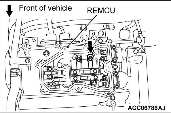
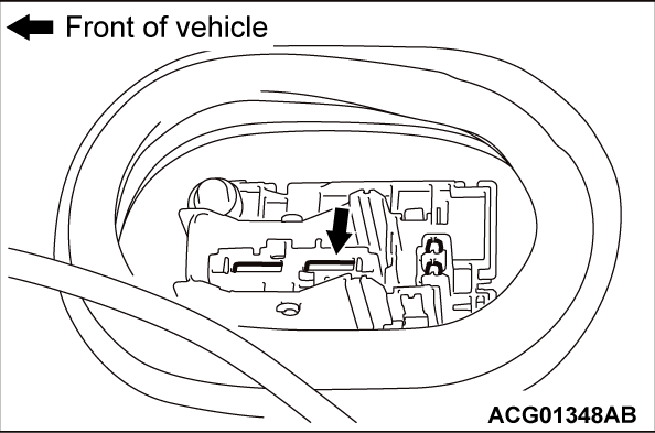
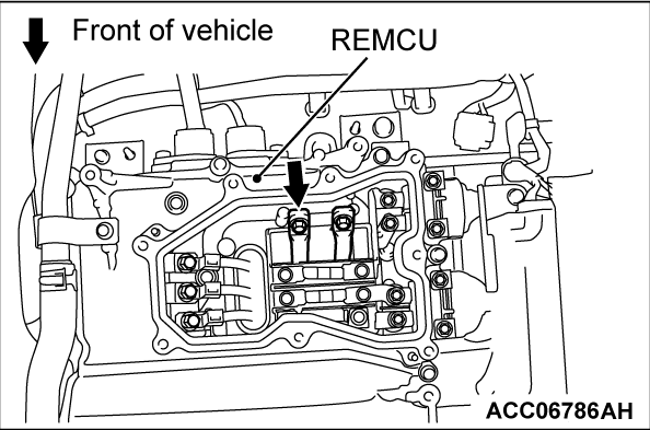
Check the wiring harness between EV control relay and the PHEV-ECU connector (terminal CNTB).
Is the check result normal?
STEP 3. Using scan tool (M.U.T.-IIISE), check whether the other DTC is set.
Check whether the FEMCU, GCU, REMCU and on board charger/DC-DC converter related DTC is set or not.
Is the DTC set?
STEP 4. Using scan tool (M.U.T.-IIISE), check whether the other DTC is set.
Check whether DTC is set in the A/C-ECU, A/C compressor assembly and electric heater-ECU (Refer to GROUP 55 - Diagnostic Trouble Code Chart  <A/C-ECU>,
  <A/C compressor assembly>,
  <electric heater-ECU>).
 <A/C-ECU>,
  <A/C compressor assembly>,
  <electric heater-ECU>).
Is the DTC set?
STEP 5. Using scan tool (M.U.T.-IIISE), check whether the DTC is set again.
| danger |
|
(1) Erase the DTC.
(2)
| danger | Isolate bare wires of the disconnected high-voltage circuit with a plastic tape. |
Disconnect the high-voltage connector at the electric heater.
(3) Turn off the power supply mode of the electric motor switch.
(4) Depress the brake pedal, and turn on the power supply mode of the electric motor switch (READY operation)*.
| note | *: When a DTC is set, you cannot make the READY (ready to drive) indicator illuminate by making the READY operation. |
(5) Check the DTC.
Is the DTC set?
STEP 6. Using scan tool (M.U.T.-IIISE), check whether the DTC is set again.
| danger |
|
(1) Erase the DTC.
(2)
| danger | Isolate bare wires of the disconnected high-voltage circuit with a plastic tape. |
Disconnect the high-voltage connector at the AC inverter <Vehicles with AC power supply>.
(3) Turn off the power supply mode of the electric motor switch.
(4) Depress the brake pedal, and turn on the power supply mode of the electric motor switch (READY operation)*.
| note | *: When a DTC is set, you cannot make the READY (ready to drive) indicator illuminate by making the READY operation. |
(5) Check the DTC.
Is the DTC set?
STEP 7. Using scan tool (M.U.T.-IIISE), check whether the DTC is set again.
| danger |
|
(1) Erase the DTC.
(2)
| danger | Isolate bare wires of the disconnected high-voltage circuit with a plastic tape. |
Disconnect the high-voltage connector at the on-board charger and DC/DC converter.
(3) Turn off the power supply mode of the electric motor switch.
(4) Depress the brake pedal, and turn on the power supply mode of the electric motor switch (READY operation)*.
| note | *: When a DTC is set, you cannot make the READY (ready to drive) indicator illuminate by making the READY operation. |
(5) Check the DTC.
Is the DTC set?
STEP 8. Using scan tool (M.U.T.-IIISE), check whether the DTC is set again.
| danger |
|
(1) Erase the DTC.
(2)
| danger | Isolate bare wires of the disconnected high-voltage circuit with a plastic tape. |
Disconnect the high-voltage connector at the A/C compressor.
(3) Turn off the power supply mode of the electric motor switch.
(4) Depress the brake pedal, and turn on the power supply mode of the electric motor switch (READY operation)*.
| note | *: When a DTC is set, you cannot make the READY (ready to drive) indicator illuminate by making the READY operation. |
(5) Check the DTC.
Is the DTC set?
STEP 9. Check the high-voltage fuse.
| danger |
|
(1) Check the high-voltage fuse No.1 (Normal Charging: 350 A) (integrated with the main drive lithium-ion battery) (Refer to  ).
).
 ).
).(2) Check the high voltage fuse No.5 [For electric heater (Integrated with the REMCU)] (Refer to  ). <Vehicles with electric heater>
 ). <Vehicles with electric heater>
(3) Check the high voltage fuse No.4 [For on-board charger/DC-DC converter (Integrated with the REMCU)] (Refer to  ).
).
 ).
).(4) Check the high voltage fuse No.6 [For AC Inverter (Integrated with junction box)] (Refer to GROUP 54A - AC power supply, On-vehicles service  ). <Vehicles with AC power supply>
 ). <Vehicles with AC power supply>
(5) Check the high voltage fuse No.3 [For A/C compressor (Integrated with power drive unit)] (Refer to  ).
).
 ).
).Is the check result normal?
: Replace the high-voltage fuse No.1 (Normal Charging: 350 A) (integrated with the main drive lithium-ion battery) (Refer to  ). Then go to Step 20
 .
.
 ). Then go to Step 20
 .
. : Replace the high voltage fuse No.5 [For electric heater (Integrated with the REMCU)] (Refer to  ). Then go to Step 20
 .
.
 ). Then go to Step 20
 .
. : Replace the high voltage fuse No.4 [For on-board charger/DC-DC converter (Integrated with the REMCU)] (Refer to  ). Then go to Step 20
 .
.
 ). Then go to Step 20
 .
.STEP 10. Check the high-voltage wiring harness.
Check whether the high-voltage wiring harness wires between the main drive lithium-ion battery and the power drive unit as well as between the main drive lithium-ion battery and the FEMCU are secured at the specified torque. (Refer to  <Power drive unit>,
  <Main drive lithium-ion battery>).
 <Power drive unit>,
  <Main drive lithium-ion battery>).
Tightening torque: 7.0 ± 2.0 N·m (62 ± 17 in-lb)
Is the check result normal?
STEP 11. Check the high-voltage wiring harness.
Check whether the high-voltage wiring harness wires between the main drive lithium-ion battery and the power drive unit as well as between the main drive lithium-ion battery and the REMCU are secured at the specified torque (Refer to  <Power drive unit>,
  <Main drive lithium-ion battery> and
  <REMCU>).
 <Power drive unit>,
  <Main drive lithium-ion battery> and
  <REMCU>).
Tightening torque: 7.0 ± 2.0 N·m (62 ± 17 in-lb)
Is the check result normal?
STEP 12. Check the high-voltage circuit.
| danger |
|
(2) Apply a voltage of 12 volts to the CNT- terminal to turn on the charging contactor.
(3) Connect a high-voltage compatible multimeter between the main drive lithium-ion battery high-voltage terminal (REMCU) and the main drive lithium-ion battery service plug rear terminal.
OK: Approximately 100 - 164 volts
(4) Apply a voltage of 12 volts to the CNTP terminal to turn on the charging contactor.
(5) Connect a high-voltage compatible multimeter between the main drive lithium-ion battery high-voltage terminal (REMCU) and the main drive lithium-ion battery service plug front terminal.
OK: Approximately 100 - 164 volts
(6) Apply a voltage of 12 volts to the CNT+ terminal to turn on the charging contactor.
(7) Connect a high-voltage compatible multimeter between the main drive lithium-ion battery high-voltage terminal (REMCU) and the main drive lithium-ion battery service plug front terminal.
OK: Approximately 100 - 164 volts
Is the check result normal?
STEP 13. Check the main drive lithium-ion battery main contactor (P) and (N) <On-vehicles check>.
Check resistance of main contactor (P) and (N) coil with harness connector (Refer to  ).
).
 ).
).Is the check result normal?
STEP 14. Check the signal line for short to ground circuit (PHEV-ECU connector and main drive lithium-ion battery connector).
Check the wiring harness between PHEV-ECU connector (terminals CNT-) and the main drive lithium-ion battery connector.
Is the check result normal?
STEP 15. Check whether the electric heater is stuck on.
| danger |
|
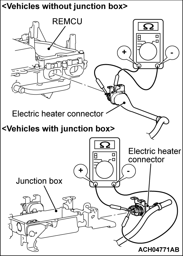
(2) Disconnect the electric heater connector (high voltage) and measure at the equipment side.
(3) Measure the resistance between electric heater connector (high voltage) (terminal No.1 and No.2).
OK: No continuity (Reference value: 1 MΩ or more)
Is the check result normal?
STEP 16. Resistor check.
(1) Check whether the terminals are loose.
(2) Check the resistance in the resistor.
Is the check result normal?
 The procedure is complete.
STEP 17. Contactor check.
Check the contactors (Refer to  ).
).
 ).
).Is the check result normal?
STEP 18. Test the OBD-II drive cycle.
(1) Carry out a test drive with the drive cycle pattern. Refer to Diagnostic Function - OBD-II Drive Cycle - Pattern 3  .
.
 .
.(2) Check the DTC.
Is the DTC set?
STEP 19. Test the OBD-II drive cycle.
(1) Carry out a test drive with the drive cycle pattern. Refer to Diagnostic Function - OBD-II Drive Cycle - Pattern 3  .
.
 .
.(2) Check the DTC.
Is the DTC set?
 Replace the power drive unit (Refer to GROUP 54Db - Power Drive Unit Removal and Installation
  ). Then go to Step 20
 .
. The inspection is complete.
![[Previous]](../../../buttons/fprev.png)
![[Next]](../../../buttons/fnext.png)
