PRECAUTIONS ON HOW TO USE THE HIGH-VOLTAGE VEHICLE
This vehicle has a high voltage circuit of 300 V <nominal value> (Depending on the remaining capacity of the battery, generate a maximum operating voltage of 336 V). If the vehicle is handled incorrectly, electric leakage or shock may result. Also, the service technicians/engineers who perform inspection and service related to the high-voltage circuit of the electric vehicles are obligated to observe national legal requirements.
INSPECTION/TEST OF PROTECTIVE EQUIPMENT, BLOTTER STORAGE
Check and store the protective equipment in accordance with national legal requirements.
PROTECTIVE EQUIPMENT (REFERENCE ONLY)
| caution | Use protective equipment which complies with national legal requirements. |
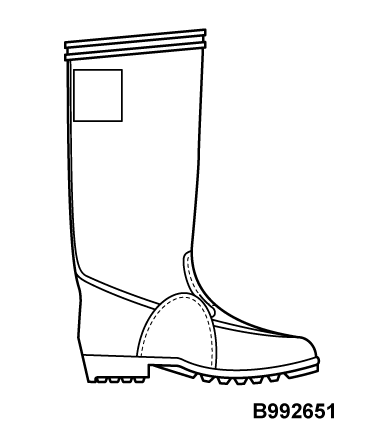
| Protective equipment | Number and name | Supersession | Application |
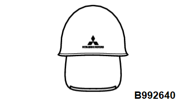
| MB992640 Electric insulation helmet (with shield) | - |
| |
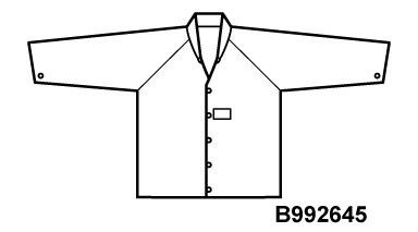
| MB992645 Electric insulation jacket | - |
| |
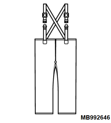
| MB992646 Electric insulation trousers | - |
| |
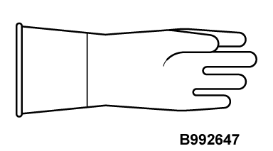
| - |
| |
| - |
|
TESTER AND SPECIAL TOOL
Be sure to use the tester and special tools specified in this manual.
HIGH-VOLTAGE COMPONENTS
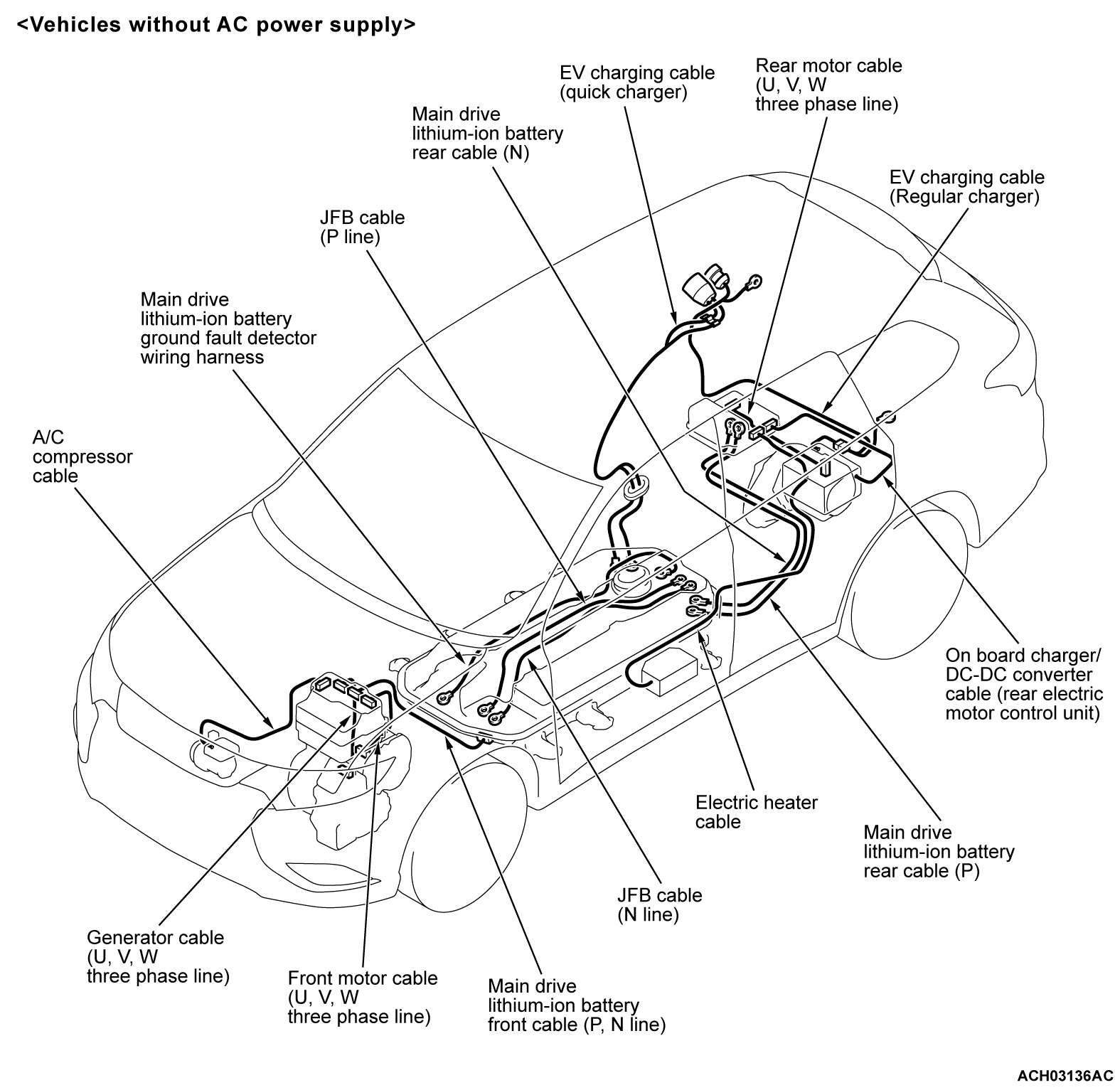
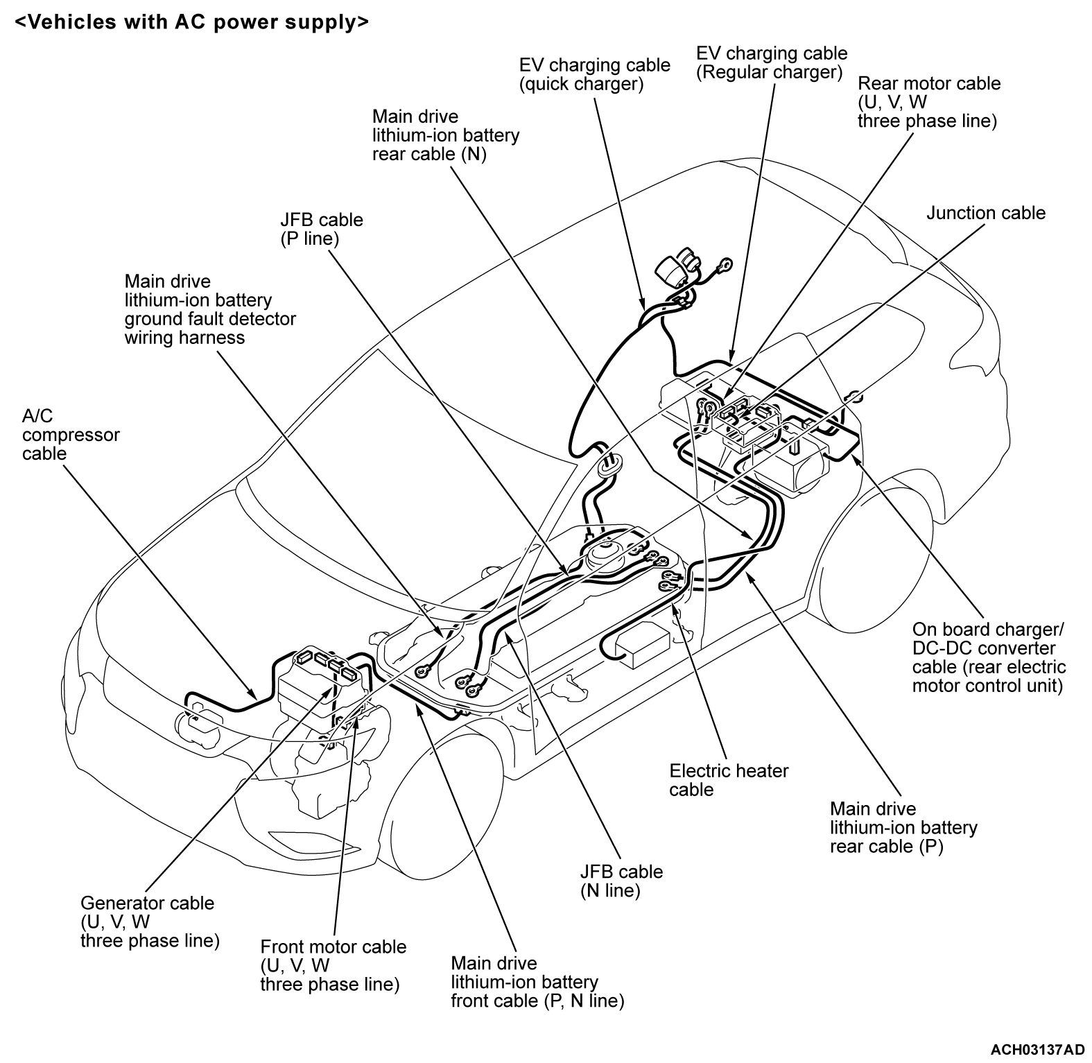
The high-voltage components are described below. Also, wiring harness and connectors of high-voltage circuit are unified with a color of orange.
- Main drive lithium-ion battery assembly
- Power drive unit (incorporating GCU [Generator Control Unit])
- Rear electric motor control unit (REMCU)
- Front motor assembly
- Rear motor assembly
- Generator
- On board charger/DC-DC converter
- Electric heater
- Main drive lithium-ion battery cable
- EV charging cable (Normal charger)
- EV charging cable (Quick charger)
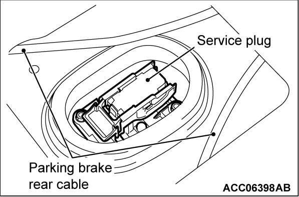
- Service plug
- Wiring harness and connector
SERVICE PRECAUTIONS
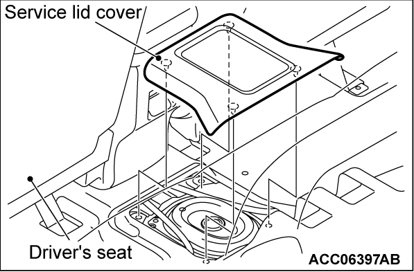
Remove the service plug under the rear center seat according to the following procedure, which shuts off the high voltage to the high-voltage system. Also, when installing the service plug and the service lid, check the precautions (Refer to  ).
).
 ).
).Service plug and service lid removal steps
2. Turn off the power supply mode of the electric motor switch.
3.
| warning |
|
Disconnect the negative terminal of the 12V starter battery.
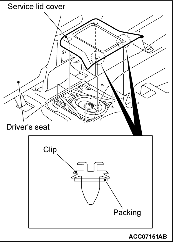
4. Remove the service lid cover.
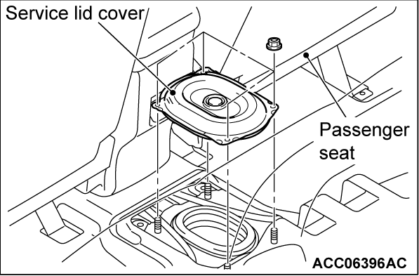
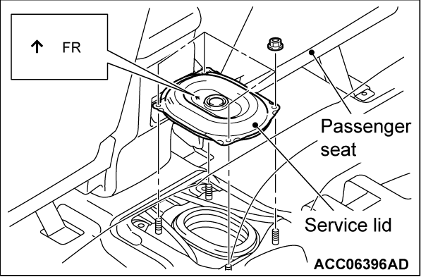
5. Remove the service lid mounting nut, and then remove the service lid.
6.
| danger |
|
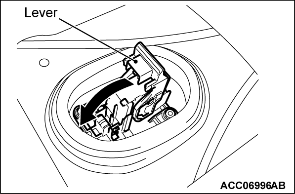
| warning | The voltage of the smoothing condenser in the inverter must be decreased thoroughly. Therefore, do not remove the service plug for 5 minutes after the negative terminal of the 12V starter battery is disconnected. |
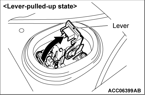
Lift the service plug lever.
7.
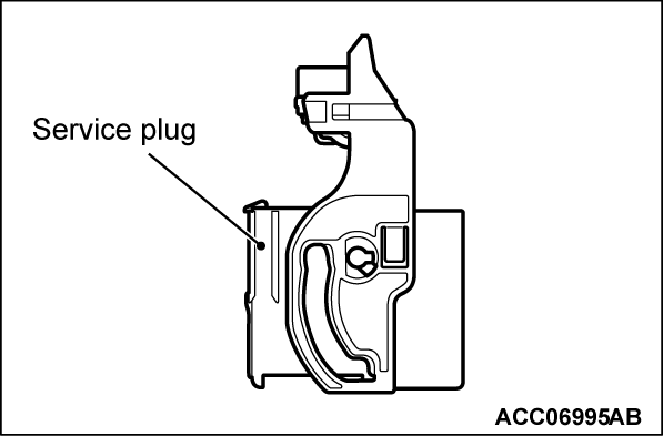
Remove the service plug.
| danger | After removing the service plug, insulate the plug installed part of the main drive lithium-ion battery securely. |
8.
| danger | During inspection, wear the electric insulation gloves. If the high voltage cannot be shut off after the inspection, refer to  . . |
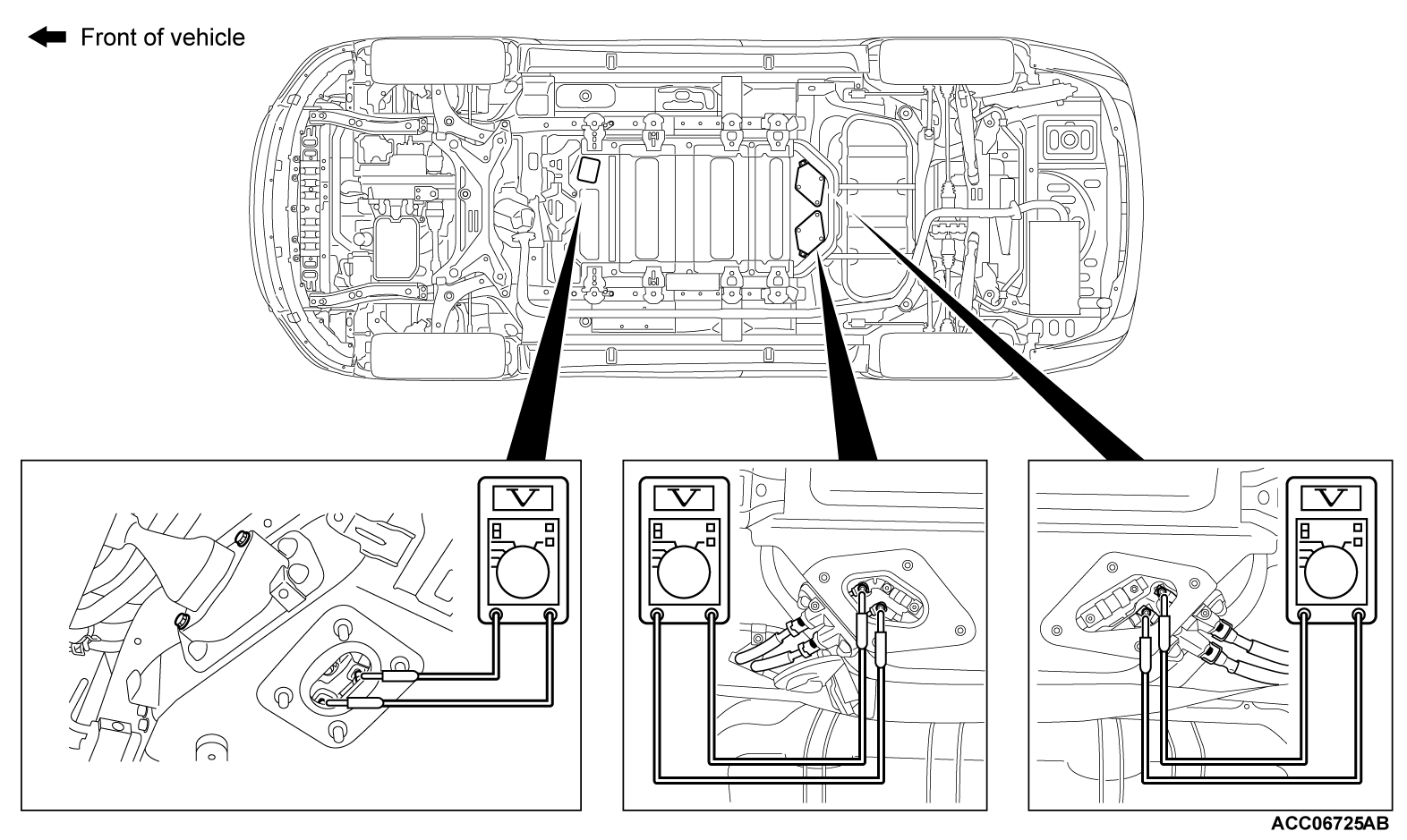
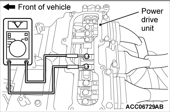
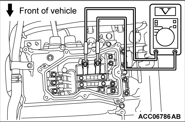
When removing and installing each high-voltage part, be sure to perform the following inspection beforehand.
When the main drive lithium-ion battery is removed and installed
Normal voltage: Approximately 0 volt
When the other high-voltage parts are removed and installed
Normal voltage: Approximately 0 volt
Normal voltage: Approximately 0 volt
SERVICE PLUG AND SERVICE LID INSTALLATION STEPS
| danger | Wear the electric insulation gloves when installing the service plug. |
1.
| caution | Pull the service plug lever down until it clicks, because the interlock switch does not operate unless the service plug lever is pulled down properly. |
Install the service plug.
2.
The arrow on the service lid should face towards the front of the vehicle.
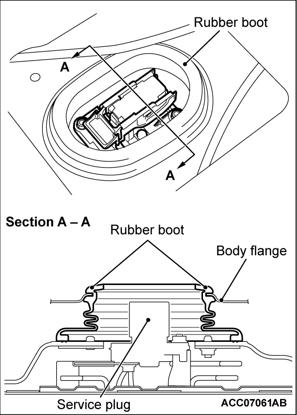
| caution | If the rubber boot around the service plug is released, water may enter the inside of the main drive lithium-ion battery, resulting in short-circuit. Therefore, check that the rubber boot is engaged with the body flange before installing the service lid. |
3. Tighten the service lid mounting nuts.
4.
| caution | The service lid cover mounting clip (two at the rear of the vehicle) is assembled with a packing to avoid water entry. When you install the service lid, make sure that this packing is not deformed or missing. |
Install the service lid cover.
ACTION WHEN HIGH VOLTAGE CANNOT BE SHUT OFF
SPECIAL TOOL (REFERENCE ONLY)
| Tool | Tool number and name | Supersession | Application | ||
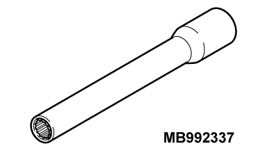
| MB992337 Electric insulation socket | - |
|
| danger | Be sure to wear the electric insulation gloves (special tool) during this work. |
| danger | Be sure to wear the electric insulation socket (MB992337) during this work. |
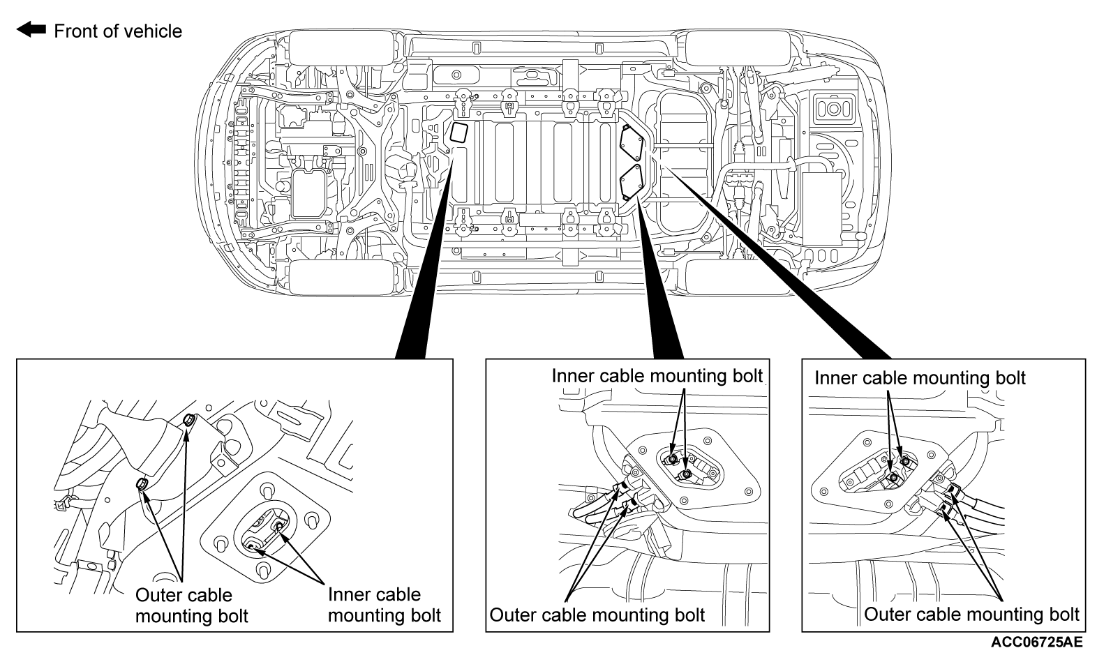
When the high voltage remains even after the shut-off of the high voltage is performed, or when the high voltage shut-off work itself is difficult because of the accidental damages, perform the security according to the following procedure.
1. Remove the work-hole lid (Refer to GROUP 54Dc - Main Drive Lithium-ion Battery Removal and Installation  ).
).
 ).
).3. Remove the six outer cable mounting bolts.
4. Pull out the main drive lithium-ion battery cable <front and rear> and the EV charger cable (quick charging) from the main drive lithium-ion battery.
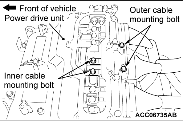
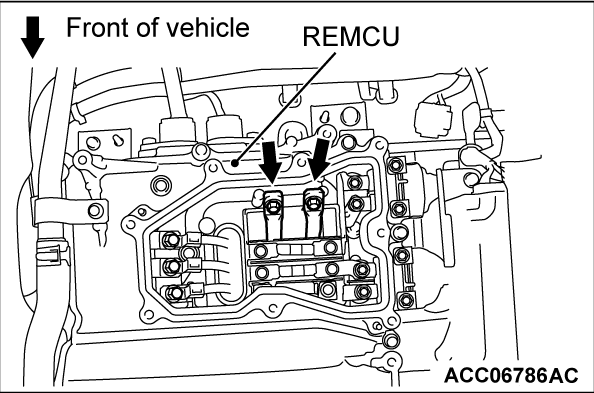
5. If steps 1 to 4 are difficult to perform or it is necessary to carry out any service work in the engine compartment or the electric motor unit compartment, disconnect the main drive lithium-ion battery cable at the power drive unit and the REMCU side (Refer to GROUP 54Db - Power Drive Unit  <Power drive unit> and GROUP 54Db - REMCU
  <REMCU>).
 <Power drive unit> and GROUP 54Db - REMCU
  <REMCU>).
ACTION WHEN HIGH-VOLTAGE SHUT-OFF SYSTEM IS OPERATED
HIGH-VOLTAGE CONNECTOR REMOVAL STEPS
| danger |
|
| caution | Be sure to release the lock of the connector with your hands, because use of a tool or others may damage the connector. |
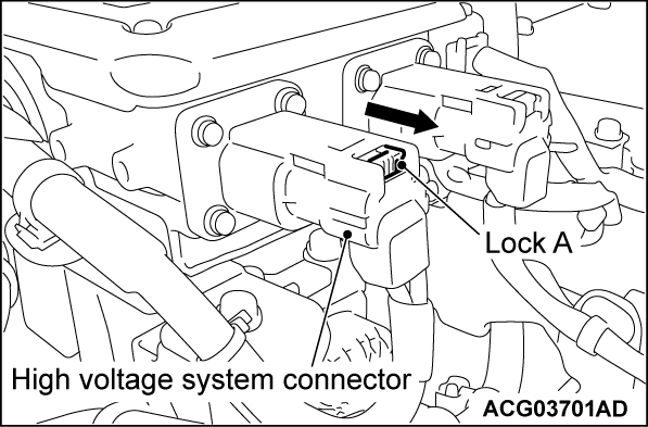
1. Slide the lock (A) towards the arrow direction to disengage it.
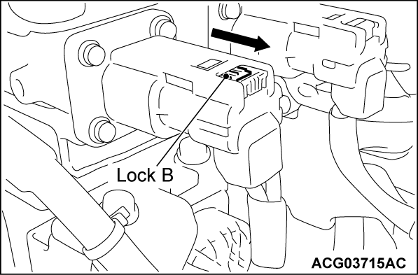
2. Depress the lock (B) and pull out the connector towards the arrow direction to its stop position.
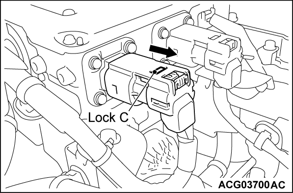
3. Depress the lock (C) and disconnect the connector by pulling out it towards the arrow direction.
![[Previous]](../../../buttons/fprev.png)
![[Next]](../../../buttons/fnext.png)
