POST-COLLISION DIAGNOSIS
Perform the inspection and service on post-collision vehicles according to the procedures below regardless of the deployment or activation statuses of air bags and seat belt pre-tensioner.
SRS-ECU MEMORY CHECK
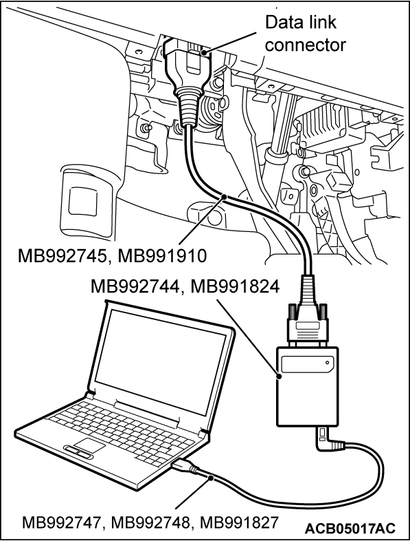
Required Special Tools:
- MB992744: Vehicle communication interface-Lite (V.C.I.-Lite)
- MB992745: V.C.I.-Lite main harness A
- MB992747: V.C.I.-Lite USB cable short
- MB992748: V.C.I.-Lite USB cable long
- MB991958: Scan Tool (M.U.T.-III Sub Assembly)
- MB991824: Vehicles Communication Interface (V.C.I.)
- MB991827: M.U.T.-III USB Cable
- MB991910: M.U.T.-III Main Harness A (Vehicles with CAN communication system)
1.
| caution | To prevent damage to scan tool (M.U.T.-IIISE), always turn off the power supply mode of the electric motor switch before connecting or disconnecting scan tool (M.U.T.-IIISE). |
2. Start up the personal computer.
3. Connect special tool MB992747/M992748 or special tool MB991827 to special tool MB992744 or special tool MB991824 and the personal computer.
4. Connect special tool MB992745 or special tool MB991910 to special tool MB992744 or special tool MB991824.
5. Connect special tool MB992745 or special tool MB991910 to the data link connector.
| note | when the special tool MB992745 is connected to the data link connector, the special tool MB992744 indicator light will be illuminated in a green color |
6. Turn the power switch of special tool MB991824 to the "ON" position. <When using the special tool MB991824>
| note | When special tool MB991824 is energized, special tool MB991824 indicator light will be illuminated in a green color. |
7. Start the M.U.T.-III system on the personal computer.
| note | Disconnecting scan tool (M.U.T.-IIISE) is the reverse of the connecting sequence, making sure that the power supply mode of the electric motor switch should be turned off. |
8. Read (and write down) all displayed DTC(s) (Refer to  ).
).
 ).
).| note | If the battery power supply has been disconnected or disrupted by the collision, scan tool (M.U.T.-IIISE) cannot communicate with the SRS-ECU. Check the battery, then check and, if necessary, repair the front wiring harness and the instrument panel wiring harness before proceeding. |
9. Read the data list (fault duration and how many times memories are erased), using scan tool (M.U.T.-IIISE) (Refer to  ).
).
 ).
).10. Erase the DTC(s), and then turn off the power supply mode of the electric motor switch.
11. Wait for at least one second, and then turn on the power supply mode of the electric motor switch again.
REPAIR PROCEDURE
<DRIVER'S, FRONT PASSENGER'S, KNEE AIR BAGS AND SEAT BELT WITH PRE-TENSIONER ARE DEPLOYED>
1. Replace the following parts with new ones.
- SRS-ECU (Refer to
 ).
). - Driver's air bag module (Refer to
 ).
). - Passenger's (front) air bag module (Refer to
 ).
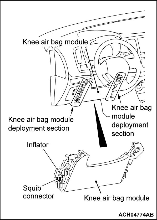
). - Knee air bag module (Refer to
 ).
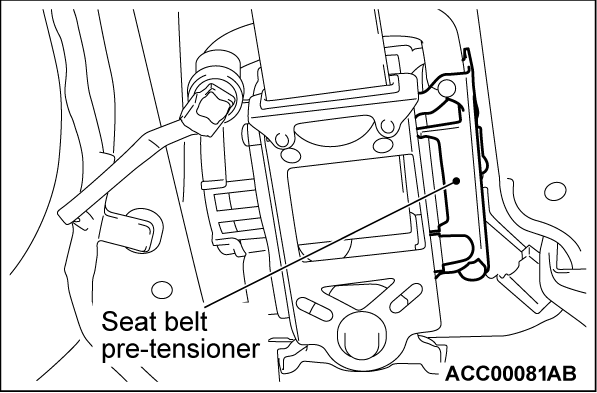
). - Seat belt with pre-tensioner (Refer to
 ).
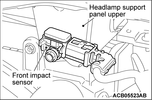
). - Front impact sensor (Refer to
 ).
). - Front seat cushion frame assembly (occupant classification-ECU and seat slide sensor) (Refer to GROUP 52A - Front Seat Assembly
 ).
).
WHEN SIDE AND CURTAIN AIR BAGS DEPLOY IN A COLLISION.
1. Replace the following parts with new ones.
2. Replace the following components of the deployed side airbag with new ones.
3. If a dent, crack, deformation, or others are visually detected in the components of the side airbag which did not deploy, replace them with new ones.
WHEN CURTAIN AIR BAGS DEPLOY IN A COLLISION.
1. Replace the following parts with new ones:
2. Check the following parts. If there is an abnormality, replace with new parts.
WHEN CURTAIN AIR BAGS DEPLOY AND SEAT BELT PRE-TENSIONER OPERATE IN A COLLISION.
1. Replace the following parts with new ones:
<AIR BAG NOT DEPLOYED BECAUSE OF LOW-SPEED COLLISION>
1. Check the SRS air bag components and seat belt assembly according to the following procedures.
2. Check the operation of seat belt. If the seat belt cannot be drawn out, replace the seat belt with a new one.
3. Visually check the seat belt components (such as pre-tensioner, retractor and buckle) for a dent, breaks, deformation, fraying. If found, replace them with new one.
SRS-ECU
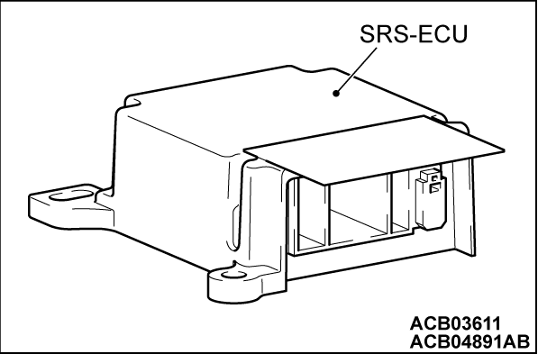
1. Check the SRS-ECU case and bracket for dent, crack, or deformation.
2. Check the connector and wiring harness for damage, and the terminal for deformation.
3. Check that SRS-ECU is installed correctly.
DRIVER'S, PASSENGER'S (FRONT) AND KNEE AIR BAG MODULE
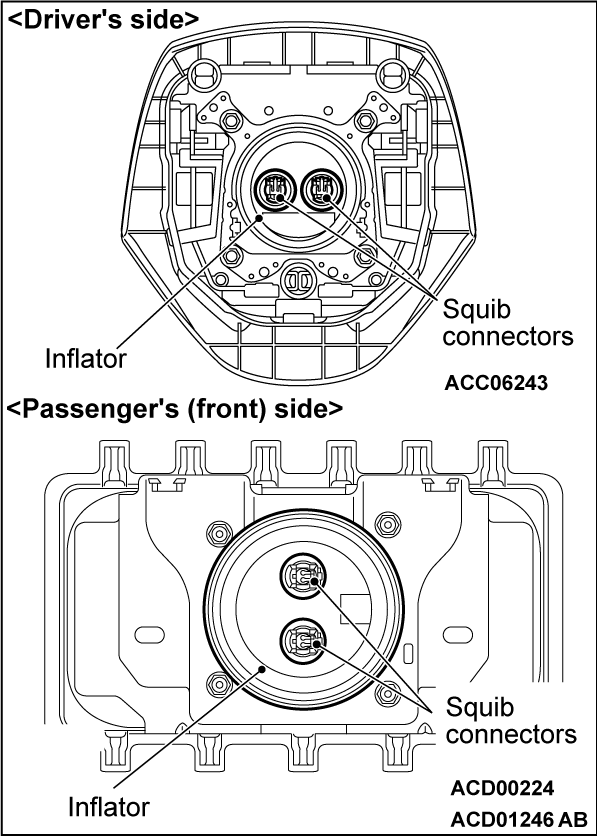
1. Check the pad cover for dent, crack, or deformation.
2. Check the connector for damage, the terminal for deformation, and the harness for binding.
3. Check the inflator case for dent, crack, or deformation.
4. Check that the air bag module is installed correctly.
CLOCK SPRING
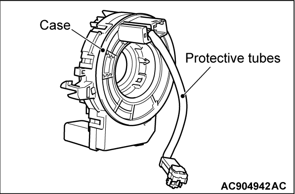
1. Check the connector and protector tube for damage, and the terminal for deformation.
2. Check the case for damage.
STEERING WHEEL, STEERING COLUMN AND SHAFT ASSEMBLY
1. Check the wiring harness (built into the steering wheel) and the connectors for damage, and the terminals for deformation.
2. Install the air bag module to check fit or alignment with the steering wheel.
3. Check the steering wheel for noise, binding or difficult operation and excessive free play.
KNEE AIR BAG MODULE
1. Check that the knee air bag deployment part of the instrument panel under cover assembly and instrument panel lower assembly is normal.
2. Check the connector for damage, the terminal for deformation, and the harness for binding.
3. Check the inflator case for dent, crack, or deformation.
4. Check that the air bag module is installed correctly.
SEAT BELT PRE-TENSIONER
1. Check the seat belt pre-tensioner crack or deformation.
2. Check the connector for damage and the terminal for deformation.
FRONT IMPACT SENSOR
1. Check the front impact sensor for dent, crack or deformation.
2. Check the connector for damage, the terminal for deformation, and the harness for binding.
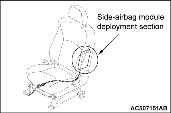
FRONT SEAT ASSEMBLY (WITH BUILT-IN SIDE AIR BAG MODULE)
1. Check that the side-airbag module deployment part of the seat is normal.
2. Check the connector for damage, the terminal for deformation, and the harness for binding.
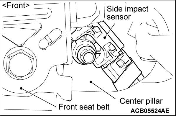
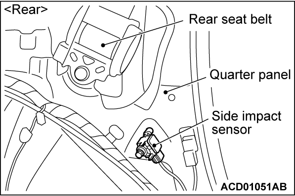
SIDE IMPACT SENSOR
1. Check the center pillar and quarter trim lower for deformation.
2. Check the side impact sensor for dent, crack, deformation, or rust.
3. Check the connector for damage, the terminal for deformation, and the harness for binding.
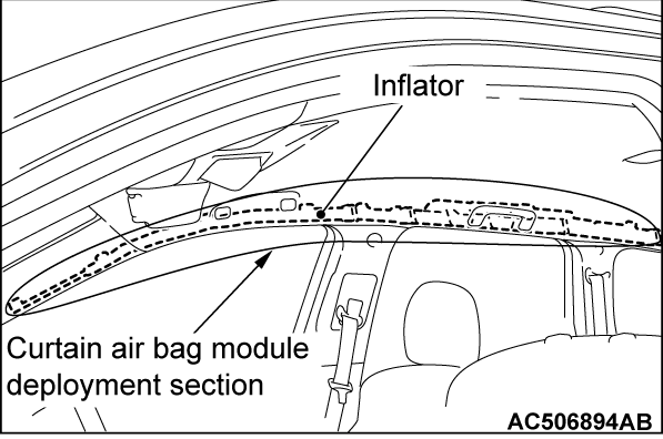
CURTAIN AIR BAG MODULE
1. Check that the curtain air bag deployment part of the headlining is normal.
2. Check the inflator surface for cracks, dents or deformations.
3. Check the connector for damage, the terminal for deformation, and the harness for binding.
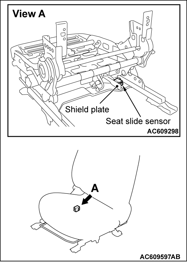
SEAT SLIDE SENSOR
1. Check that there is no connector damage, bent terminals or harness crimping.
2. Check the installation of the seat slide sensor.
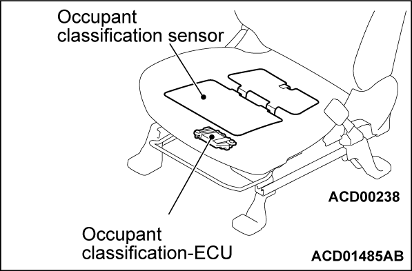
OCCUPANT CLASSIFICATION-ECU AND OCCUPANT CLASSIFICATION SENSOR
1. Check the occupant classification-ECU case and occupant classification sensor for dents, cracks or deformation.
2. Check the connector for damage, and the terminals for deformation.
3. Check the installation of the occupant classification-ECU and occupant classification sensor.
4. Check the DTC of occupant classification-ECU and replace the seat cushion frame assembly <passenger’s side>.
HIGH VOLTAGE SHUTDOWN SYSTEM OPERATES
2. Check the mounting bolts for the above component. If there is an abnormality, replace them with new ones.
3. Check the connector for damage, the terminal for deformation and the harness for binding.
![[Previous]](../../../buttons/fprev.png)
![[Next]](../../../buttons/fnext.png)
