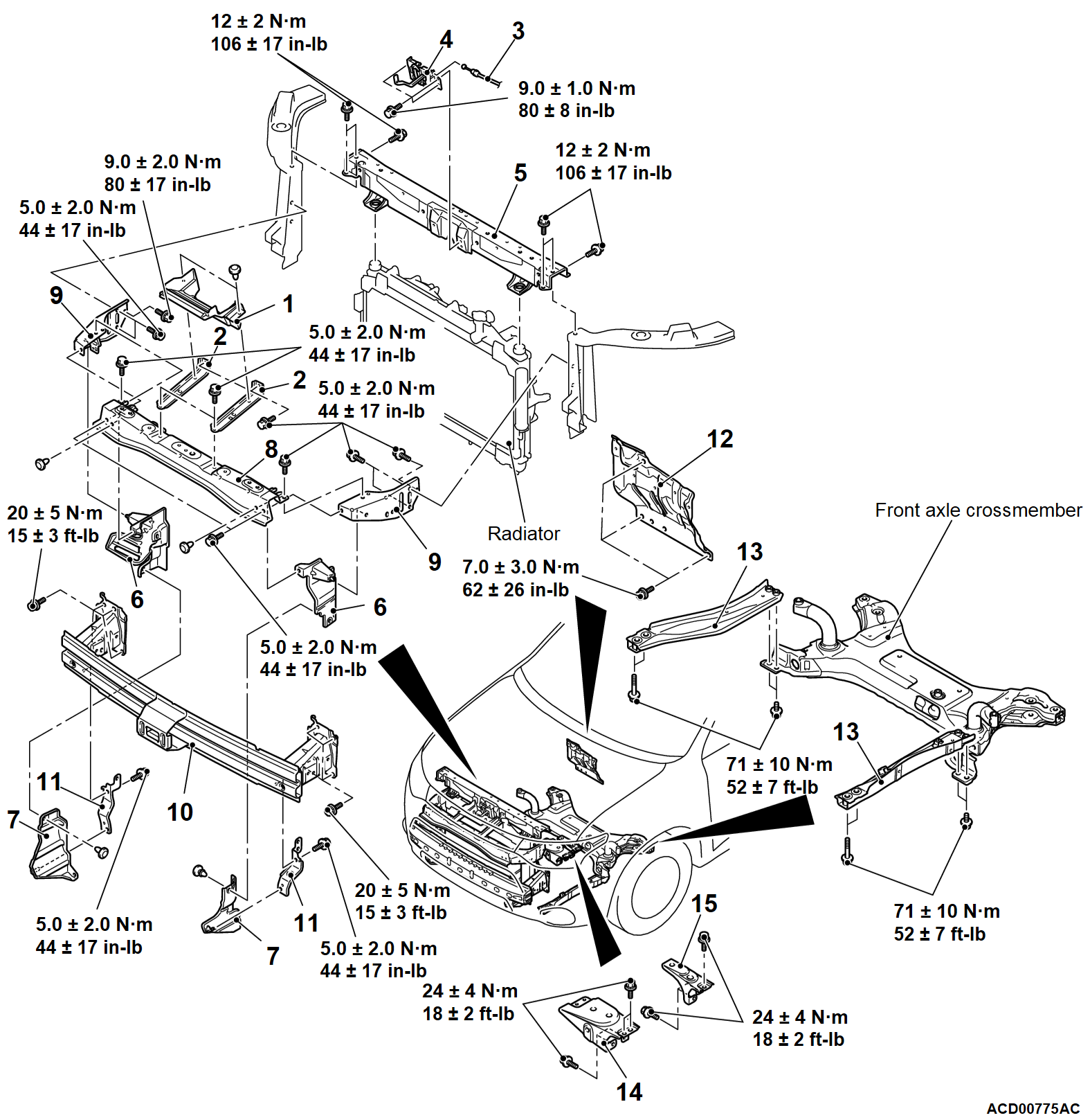
| | • | Radiator grille (Refer to GROUP 51 - Radiator Grille  .) .) |
| | 1. | Latch cover |
| | 2. | Front bumper reinforcement stay |
| | • | Radiator grille (Refer to GROUP 51 - Radiator Grille  .) .) |
| | 1. | Latch cover |
| | 2. | Front bumper reinforcement stay |
| | 3. | Hood lock release cable |
| | 4. | Hood latch |
| | • | Front impact sensor (Refer to GROUP 52B - Front Impact Sensor  .) .) |
| | • | Support upper insulator (Refer to GROUP 14 - Radiator  .) .) |
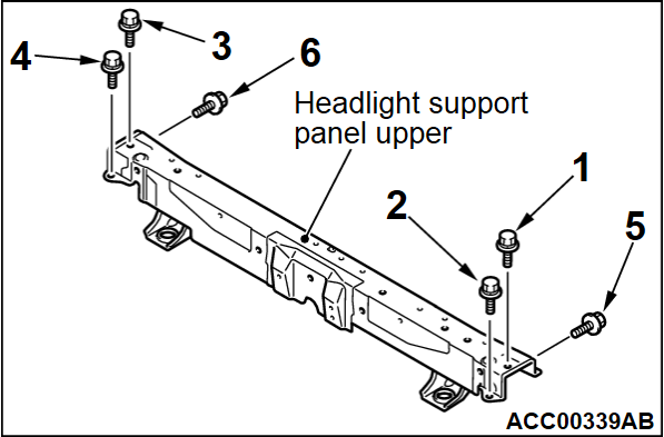
| >>E<< | 5. | Headlight support panel upper |
| | • | Front bumper assembly (Refer to GROUP 51 - Front Bumper Assembly  .) .) |
| | 6. | Airguide upper |
| | 7. | Airguide lower |
| | • | Radiator grille (Refer to GROUP 51 - Radiator Grille  .) .) |
| | 1. | Latch cover |
| | 2. | Front bumper reinforcement stay |
| | • | Front bumper assembly (Refer to GROUP 51 - Front Bumper Assembly  .) .) |
| | 6. | Airguide lower |
| | 7. | Airguide upper |
| | 8. | Front bumper reinforcement A |
| | • | Radiator grille (Refer to GROUP 51 - Radiator Grille  .) .) |
| | 1. | Latch cover |
| | 2. | Front bumper reinforcement stay |
| | • | Front bumper assembly (Refer to GROUP 51 - Front Bumper Assembly  .) .) |
| | 6. | Airguide lower |
| | 7. | Airguide upper |
| | 8. | Front bumper reinforcement A |
| | 9. | Front bumper side reinforcement |
| | • | Front bumper assembly (Refer to GROUP 51 - Front Bumper Assembly  .) .) |
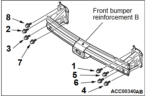
| >>D<< | 10. | Front bumper reinforcement B |
| | • | Engine room under cover front A (Refer to GROUP 51 - Under Cover  .) .) |
| | 11. | Front bumper side reinforcement lower |
| | 12. | Dash panel heat protector |
| | • | Battery tray (Refer to GROUP 54A - Battery  .) .) |
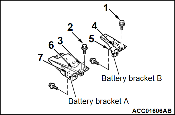
| >>C<< | 14. | Battery bracket A |
| >>C<< | 15. | Battery bracket B |
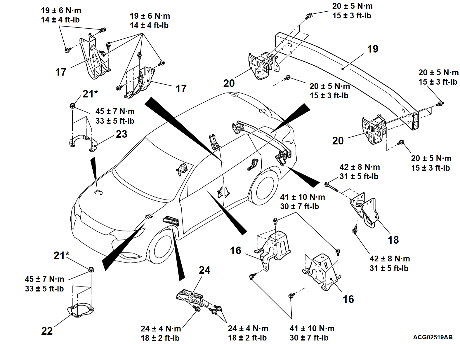
| | • | Second seat assembly (Refer to GROUP 52A - Second Seat  .) .) |
| | 16. | Body loose panel bracket |
| | • | Quarter trim, lower (Refer to GROUP 52A - Interior Trim  .) .) |
| | 17. | Rear wheelhouse inner panel brace |
| | • | Rear bumper assembly (Refer to GROUP 51 - Rear Bumper Assembly  .) .) |
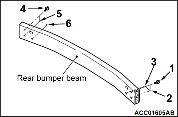
| >>B<< | 19. | Rear bumper beam |
| | 20. | Rear bumper reinforcement |
| | 21. | Strut mounting nut |
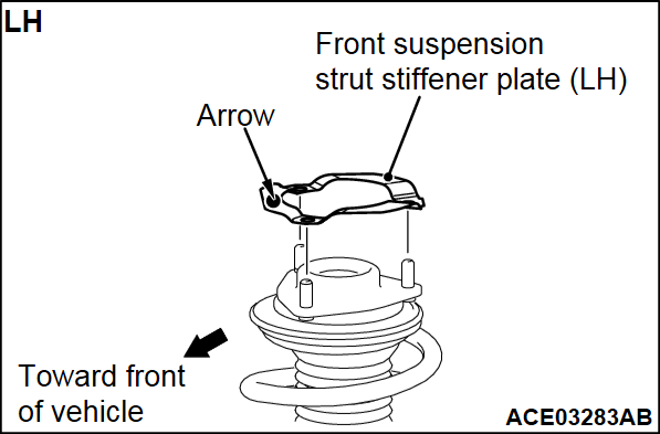
| >>A<< | 22. | Front suspension strut stiffener plate (LH) |
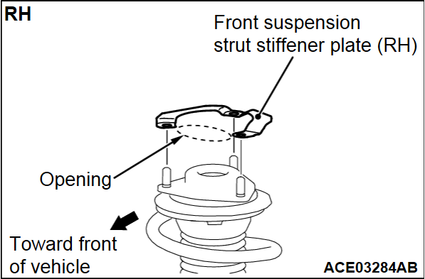
| >>A<< | 23. | Front suspension strut stiffener plate (RH) |
| | • | Fender (Refer to  ). ). |
| | 24. | Upper frame to front pillar brace |
![[Previous]](../../../buttons/fprev.png)
![[Next]](../../../buttons/fnext.png)
