REMOVAL AND INSTALLATION
Pre-removal Operation | Post-installation Operation |
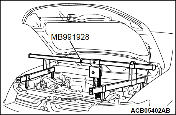
- MB991928: Engine Hanger
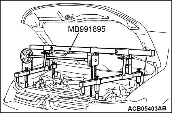
- MB991895: Engine Hanger
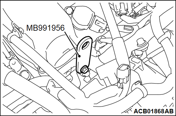
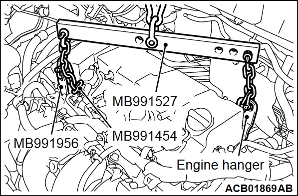
- MB991956: Engine Hanger Plate
- MB991527: Hanger
- MB991454: Engine Hanger Balancer
Required Special Tools:
REMOVAL SERVICE POINTS
<<A>> CRANKSHAFT PULLEY REMOVAL
When removing the crankshaft pulley, slightly loosen the water pump pulley mounting bolts before removal of the drive belt.
<<B>> ENGINE MOUNTING BRACKET REMOVAL
1. Secure special tool engine hanger (MB991928 or MB991895) for holding the engine assembly (Refer to GROUP 23A -Transaxle Assembly  ).
).
 ).
).2. Install special tool engine hanger plate (MB991956) to the motor bracket mounting of the cylinder head.
3. Set the following special tools to special tool MB991956 and the engine hanger to hold the engine assembly.
- Hanger (MB991527)
- Chain of engine hanger balancer (MB991454)
4. Adjust the special tool not to allow the weight of the engine and transaxle assembly to rest on the engine mounting bracket. Then remove the engine mounting bracket.
INSTALLATION SERVICE POINTS
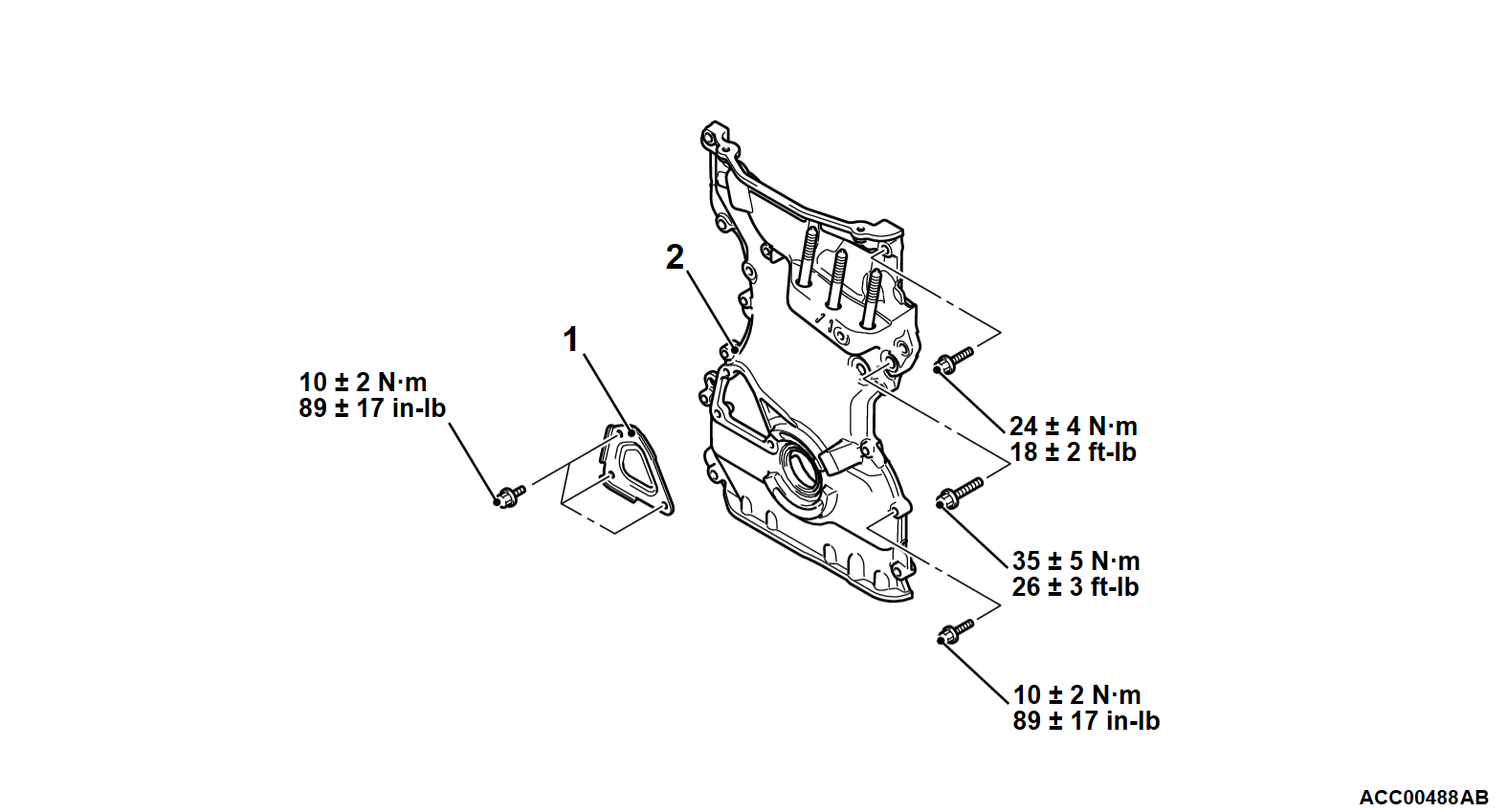
>>A<< TIMING CHAIN CASE ASSEMBLY INSTALLATION
>>B<< ENGINE MOUNTING BRACKET INSTALLATION
Use the special tool as during removal to install the engine mounting bracket.
>>C<< WATER PUMP PULLEY INSTALLATION
Temporarily tighten the water pump pulley mounting bolts. Then, tighten them to the specified torque after the installation of drive belt.
Tightening torque: 9.0 ± 1.0 N·m (80 ± 9 in-lb)
![[Previous]](../../../buttons/fprev.png)
![[Next]](../../../buttons/fnext.png)
