REMOVAL AND INSTALLATION
| caution |
REMOVAL SERVICE POINTS
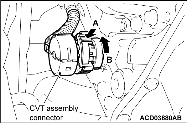
<<A>> CVT ASSEMBLY CONNECTOR DISCONNECTION
While pressing A in the figure, turn B counterclockwise to unlock the CVT assembly connector, and disconnect the connector.
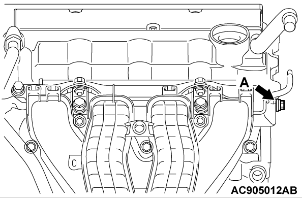
<<B>> INJECTOR PROTECTOR MOUNTING BOLT REMOVAL
Remove the injector protector mounting bolt (A shown in the illustration).
<<C>> TORQUE CONVERTER AND DRIVE PLATE COUPLING BOLT REMOVAL
1. Remove the coupling bolts while turning the crankshaft.
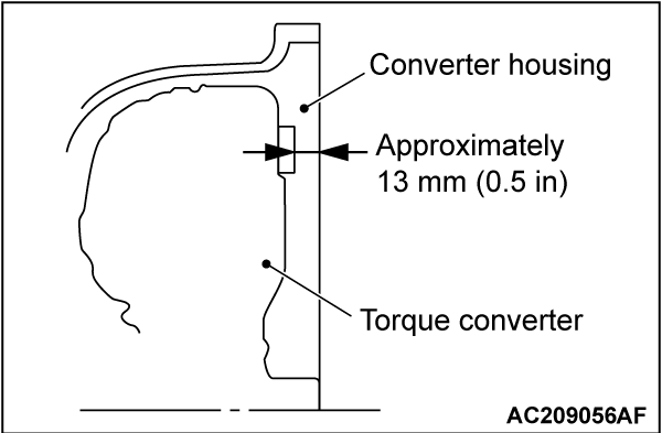
2. Fully push the torque converter into the transaxle side so that it does not remain on the engine side.
<<D>> TRANSAXLE ASSEMBLY UPPER PART COUPLING BOLT REMOVAL
Only loosen the bolts from the engine and transaxle assembly (do not remove).
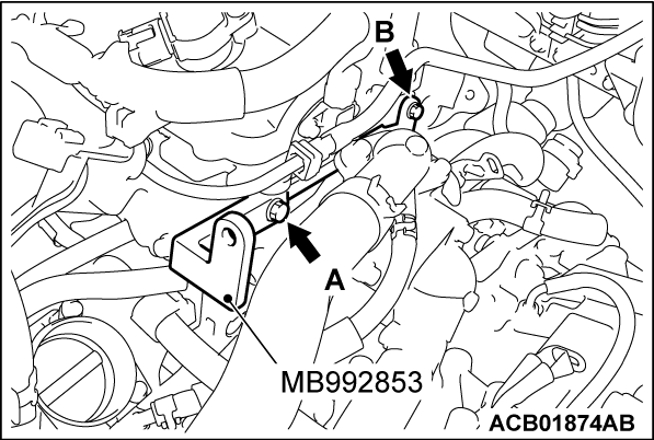
<<E>> ENGINE ASSEMBLY HOLDING
1. Tighten the engine hanger plate (special tool: MB992853) to the specified torque at A in the figure (injector protector rear mounting bolt) and B in the figure (vacuum pipe assembly mounting bolt).
Tightening torque: 20 ± 2 N·m (15 ± 1 ft-lb) (A in the figure)
Tightening torque: 11 ± 1 N·m (98 ± 8 in-lb) (B in the figure)
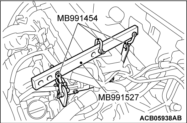
2. Assemble the engine hanger (special tool: MB991527) with the chain of the engine hanger balancer (special tool: MB991454).
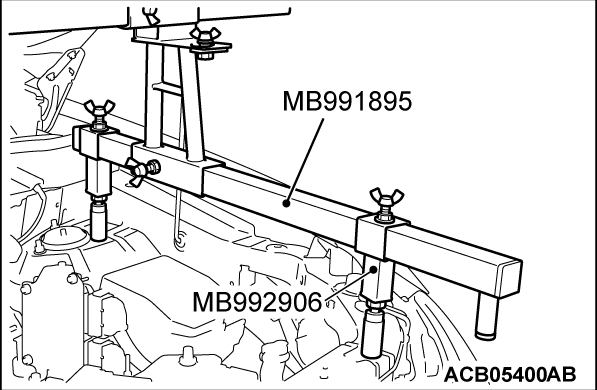
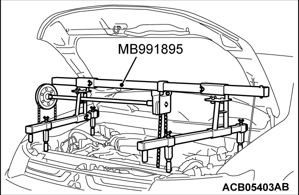
3. Set the foot of special tool engine hanger (MB991895) as shown in the figure.
| note | Slide the front foot of special tool engine hanger attachment (Special tool: MB992906) to balance the engine hanger. |
4. Connect the engine hanger (Special tool: MB991895) to the engine hanger (special tool: MB991527). Remove the garage jack and then remove the transaxle assembly upper part coupling bolts that have been loosened previously.
INSTALLATION SERVICE POINTS
>>A<< TRANSAXLE ASSEMBLY INSTALLATION
Fully push the torque converter into the transaxle side, and then assemble the transaxle assembly to the engine.
>>B<< INJECTOR PROTECTOR MOUNTING BOLT INSTALLATION
Tighten the injector protector mounting bolt (A in the figure) to the specified torque.
Tightening torque: 20 ± 2 N·m (15 ± 1 ft-lb)
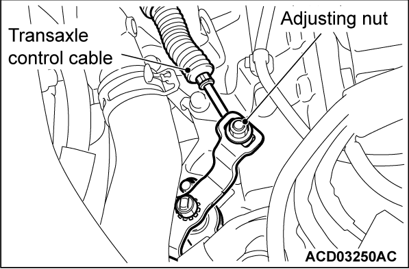
>>C<< TRANSAXLE CONTROL CABLE INSTALLATION
1. Move the selector lever to the "N" range.
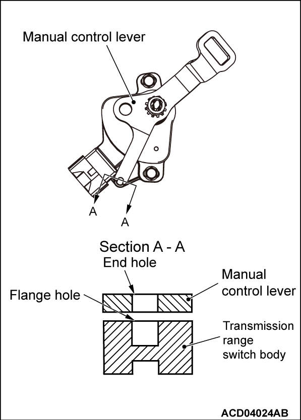
2. Move the manual control lever to Neutral position.
3. Align the hole at the end of the manual control lever and the hole in the transmission range switch body flange (section A - A).
| note | Insert a Φ5 bar into the aligned holes in the transmission range switch body flange and on the tip of the manual control lever to position the transmission range switch body. |
4. Use the adjusting nut to tighten the transaxle control cable to the specified torque.
Tightening torque: 9.5 ± 3.5 N·m (84 ± 30 in-lb)
5. Make sure that the transaxle side ranges that are corresponding to the selector lever position operate and function without fail.
![[Previous]](../../../buttons/fprev.png)
![[Next]](../../../buttons/fnext.png)

