INSULATION DETERIORATION INSPECTION
| caution |
|
| note |
|
Required Special Tools:
- MB991223: Wiring harness set
- MB992006: Extra fine probe
- MB992355: Electric insulation tester
1. INSULATION RESISTANCE CHECK OF SERVICE PLUG BOX
| danger | Make sure to attach the battery module terminal cover except when working on the relevant part. |
1. Remove the battery tray cover from the drive battery (Refer to BATTERY TRAY COVER REMOVAL AND INSTALLATION ).
).
 ).
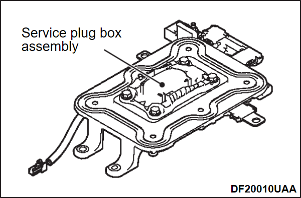
).2. Remove the service plug box with the service plug box bus bar attached (Refer to SERVICE PLUG BOX ASSEMBLY REMOVAL AND INSTALLATION ).
).
 ).
).3. Use the special tool electric insulation tester (MB992355), and set the range to 1,000 V.
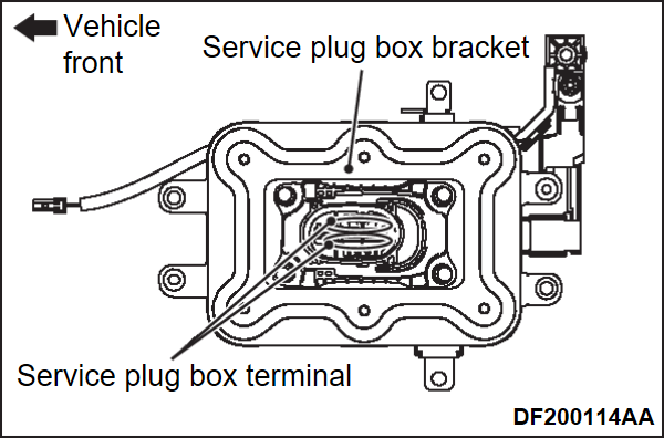
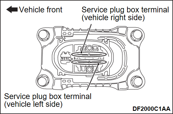
4. Measure the insulation resistance between the service plug box terminals (two parts) and ground terminal (service plug box bracket).
|
2. CHECK OF SERVICE PLUG BOX BUS BAR COVERING
| danger | Make sure to attach the battery module terminal cover except when working on the relevant part. |
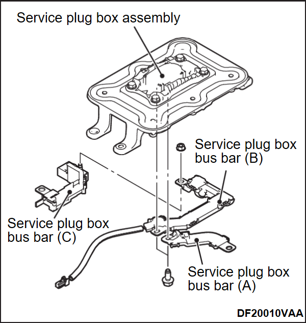
1. Remove the following bus bars from the service plug box.
- Service plug box bus bar (A)
- Service plug box bus bar (B)
- Service plug box bus bar (C)
3. LEAK VOLTAGE CHECK OF CELL VOLTAGE HARNESS
| danger | Make sure to attach the battery module terminal cover except when working on the relevant part. |
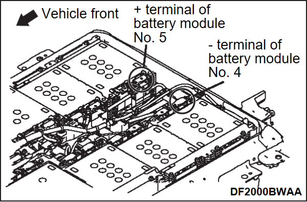
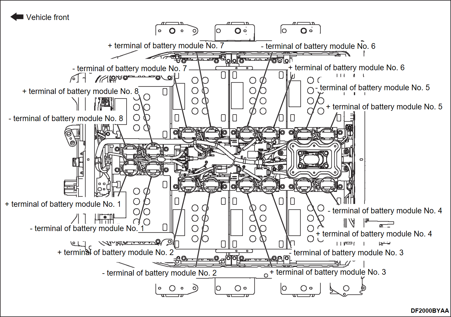
1. Using a high voltage multimeter, measure the voltage between the battery module terminals (+ terminal of No. 5, - terminal of No. 4) and ground terminal (battery upper plate).
| note | After setting the probe, wait for enough time to measure the stable voltage. |
|
- When the voltage is normal, replace the BMU (Refer to BMU REMOVAL AND INSTALLATION
 ). Then, go to
- When the voltage is not normal, go to

4. LEAK VOLTAGE CHECK AFTER DISCONNECTING CELL VOLTAGE WIRING HARNESS CONNECTOR
| danger | Make sure to attach the battery module terminal cover except when working on the relevant part. |
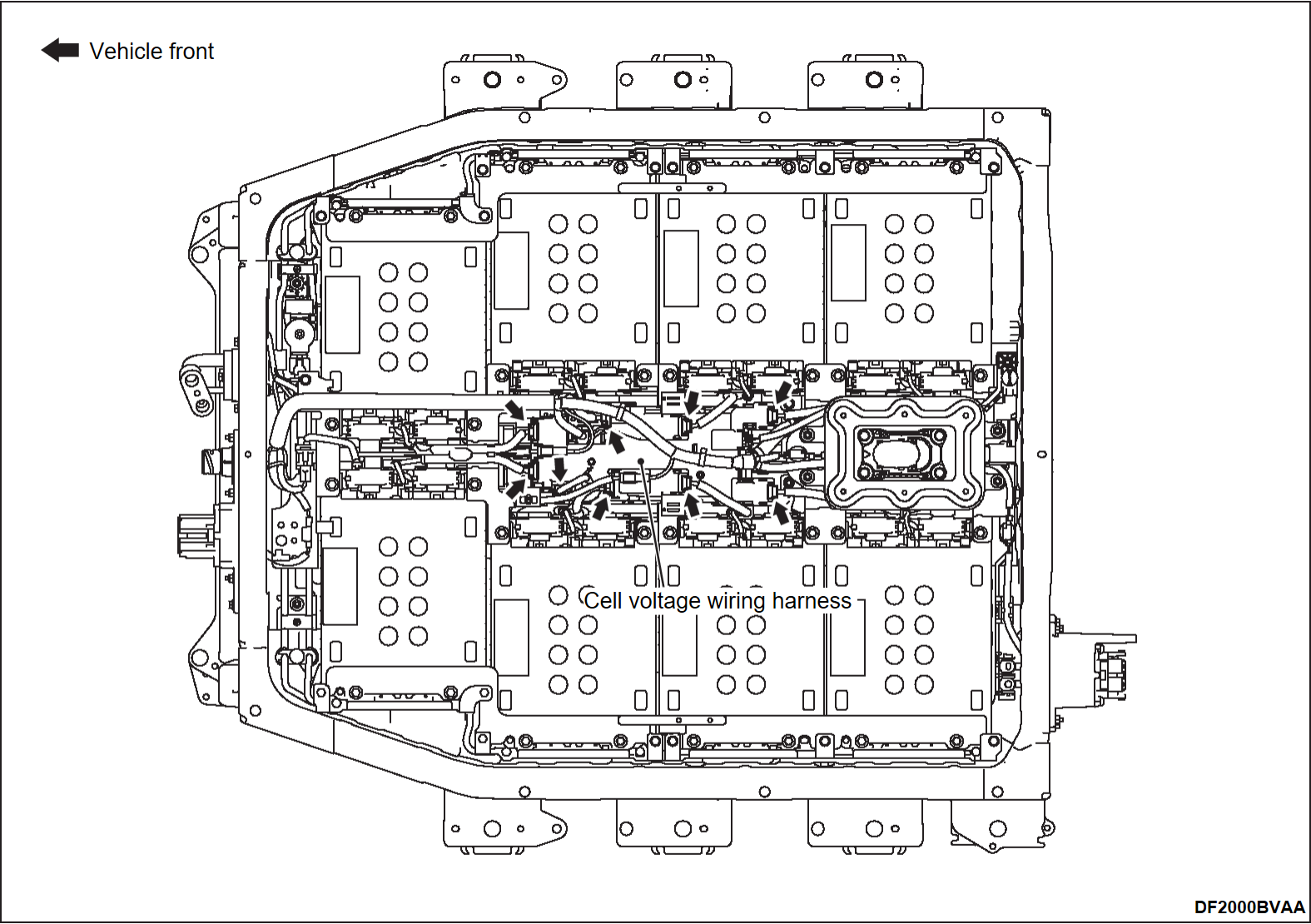
2. Using a high voltage multimeter, measure the voltage between the battery module terminals (+ terminal of No. 5, - terminal of No. 4) and ground terminal (battery upper plate).
| note | Wait for 1 minute or more before measuring the voltage. |
|
- When the voltage is normal, replace the cell voltage wiring harness (Refer to BATTERY CONTORL HARNESS AND CELL VOLTAGE HARNESS REMOVAL AND INSTALLATION
 ). Then, go to
- When the voltage is not normal, go to

5. CHECK OF BATTERY MODULE BUS BAR COVERING
| danger | Make sure to attach the battery module terminal cover except when working on the relevant part. |
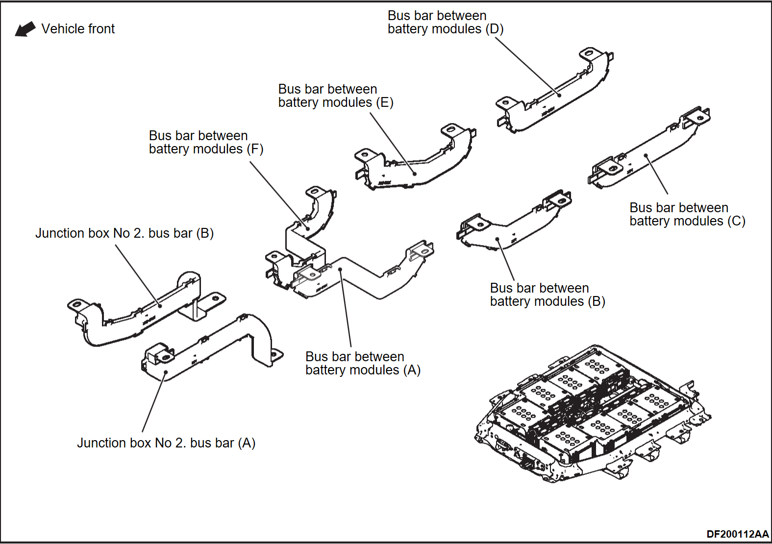
1. Remove the following bus bars.
- Junction box No 2. bus bar (A) (Refer to JUNCTION BOX NO.2 REMOVAL AND INSTALLATION
 )
) - Bus bar between battery modules (A) (Refer to BATTERY UPPER PLATE AND BATTERY MODULE BUS BAR REMOVAL AND INSTALLATION
 )
) - Bus bar between battery modules (B) (Refer to BATTERY UPPER PLATE AND BATTERY MODULE BUS BAR REMOVAL AND INSTALLATION
 )
) - Bus bar between battery modules (C) (Refer to JUNCTION BOX NO.2 REMOVAL AND INSTALLATION
 )
) - Bus bar between battery modules (D) (Refer to JUNCTION BOX NO.2 REMOVAL AND INSTALLATION
 )
) - Bus bar between battery modules (E) (Refer to BATTERY UPPER PLATE AND BATTERY MODULE BUS BAR REMOVAL AND INSTALLATION
 )
) - Bus bar between battery modules (F) (Refer to BATTERY UPPER PLATE AND BATTERY MODULE BUS BAR REMOVAL AND INSTALLATION
 )
) - Junction box No 2. bus bar (B) (Refer to JUNCTION BOX NO.2 REMOVAL AND INSTALLATION
 )
)
2. Check that there is no damage on the covering of the bus bars.
6. LEAK VOLTAGE CHECK OF BATTERY MODULE
| danger | Make sure to attach the battery module terminal cover except when working on the relevant part. |
1. Polish the drive battery high voltage connector base using a file etc.
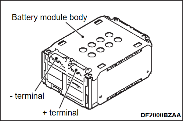
2. Using a high voltage multimeter, measure the voltage between the +/- terminal of each battery module and ground terminal (drive battery high voltage connector base).
|
7. INSULATION RESISTANCE CHECK OF BATTERY MODULE
1. Remove the battery module which is judged as a faulty part in "LEAK VOLTAGE CHECK OF BATTERY MODULE" from the drive battery tray.
2.
| caution | As there is a risk of part failure, be careful for the measuring range, and not to measure the insulation resistance by applying DC 1,000 V. |
Use the special tool electric insulation tester (MB992355), and set the range to 500 V.
3. Measure the insulation resistance between +/- terminal of the battery module and ground terminal (battery module body). After the measurement, go to 

|
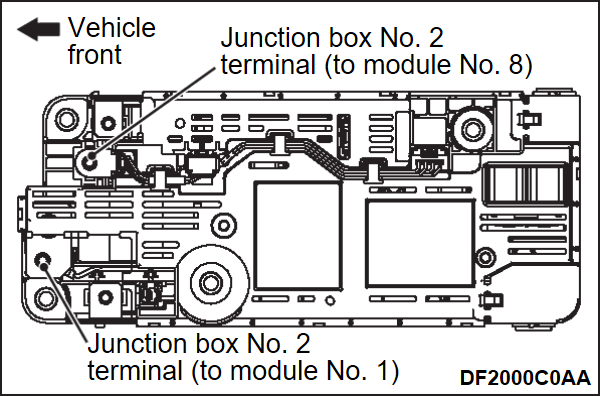
8. INSULATION RESISTANCE CHECK OF JUNCTION BOX NO. 2 (MODULE SIDE TERMINAL)
1. Use the special tool electric insulation tester (MB992355), and set the range to 1,000 V.
2. Polish the drive battery high voltage connector base using a file etc.
3. Measure the insulation resistance between the junction box No. 2 terminal and ground terminal (drive battery high voltage connector base).
|
9. INSPECTION RESULT CONFIRMATION
Confirm the faulty parts recorded in the previous procedures.
10. LEAK VOLTAGE CHECK OF DRIVE BATTERY MODULE SYSTEM
1. Assemble the drive battery just before the battery tray cover installation (Refer to SERVICE PROCEDURE ).
).
 ).
).2. Polish the drive battery high voltage connector base using a file etc.
3. Using a high voltage multimeter, measure the voltage between the following service plug box terminals and ground terminal (drive battery high voltage connector base).
|
![[Previous]](../../../buttons/fprev.png)
![[Next]](../../../buttons/fnext.png)
