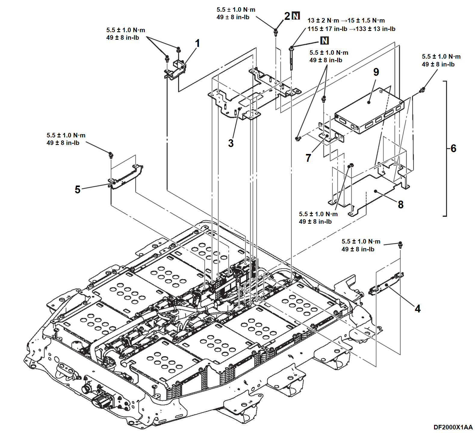
4. BMU REMOVAL AND INSTALLATION
| danger | When servicing the high voltage components, be sure to wear an insulating protective equipment to measure the high voltage (Refer to PRECAUTIONS ON HOW TO USE THE HIGH-VOLTAGE VEHICLE ). ). |
| caution |
|
Required Special Tools:
- MB992915: Electric insulation sheet
INSTALLATION SERVICE POINTS
>>A<< BATTERY UPPER PLATE (D) INSTALLATION
1. Install the battery upper plate (D), and temporarily tighten the battery upper plate (D) mounting bolts to the specified torque.
Tightening torque: 13 ± 2 N·m (115 ± 17 in-lb)
2. Fully tighten the battery upper plate (D) mounting bolts to the specified torque..
Tightening torque: 15 ± 1.5 N·m (133 ± 13 in-lb)
![[Previous]](../../../buttons/fprev.png)
![[Next]](../../../buttons/fnext.png)
