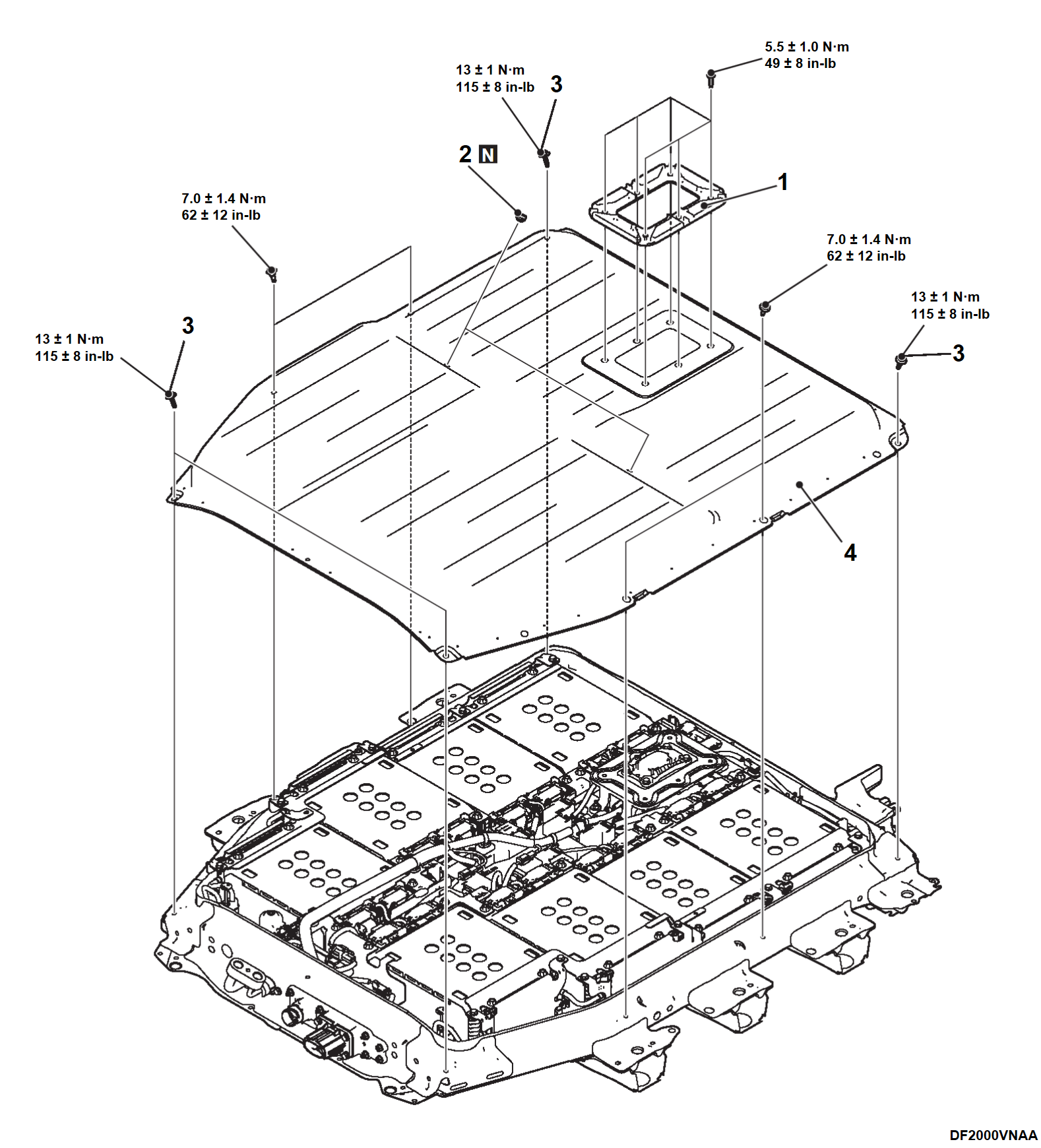
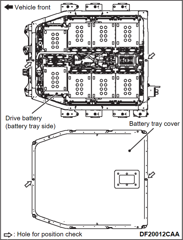
1. BATTERY TRAY COVER REMOVAL AND INSTALLATION
| danger | When servicing the high voltage components, be sure to wear an insulating protective equipment to measure the high voltage (Refer to PRECAUTIONS ON HOW TO USE THE HIGH-VOLTAGE VEHICLE ). ). |
Required Special Tools:
- MB992915: Electric insulation sheet
REMOVAL SERVICE POINTS
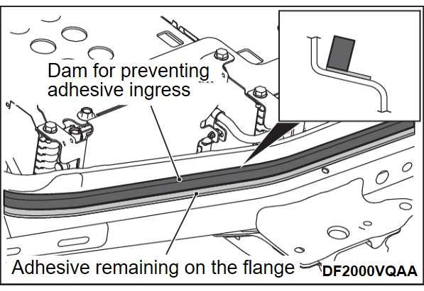
<<A>> BATTERY TRAY COVER ASSEMBLY REMOVAL
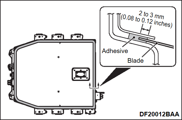
1. Use a box cutter to make a cut for approximately 2 to 3 mm (0.08 to 0.12 inches) all around drive battery.
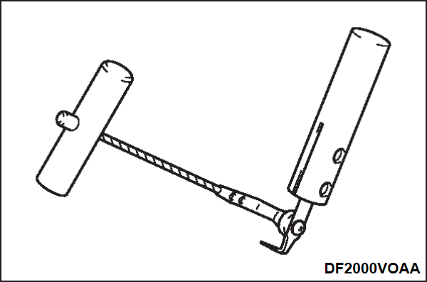
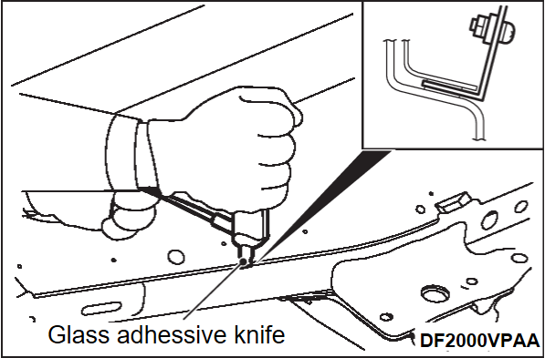
2. Use a glass adhesive knife. [Blade length: 48 mm (1.89 inches)]
| note | Prepare the blade spare due to the possibility that the blade of the glass adhesive knife will break during work. |
3. While holding the glass adhesive knife and the end of battery tray cover at right angle, pull the blade of the glass adhesive knife parallel to the end of the battery tray cover to detach the adhesive.
4.
| caution |
|
Remove the battery tray cover so that the chips do not get inside the drive battery.
5.
| caution |
|
Scrape away the remaining adhesive on the flange of the battery tray cover and battery tray assembly with a sharp knife etc. around the whole circumference so that the thickness is approximately 1 to 2 mm (0.04 to 0.08 inches).
6. Remove the chip of adhesive cleanly.
INSTALLATION SERVICE POINTS
>>A<< BATTERY TRAY COVER ASSEMBLY INSTALLATION
1. Degrease and clean the surface of the adhesive remaining on the flange part of the battery tray assembly and battery tray cover using Mitsubishi Genuine Parts Cleaner (MZ100387) or equivalent.
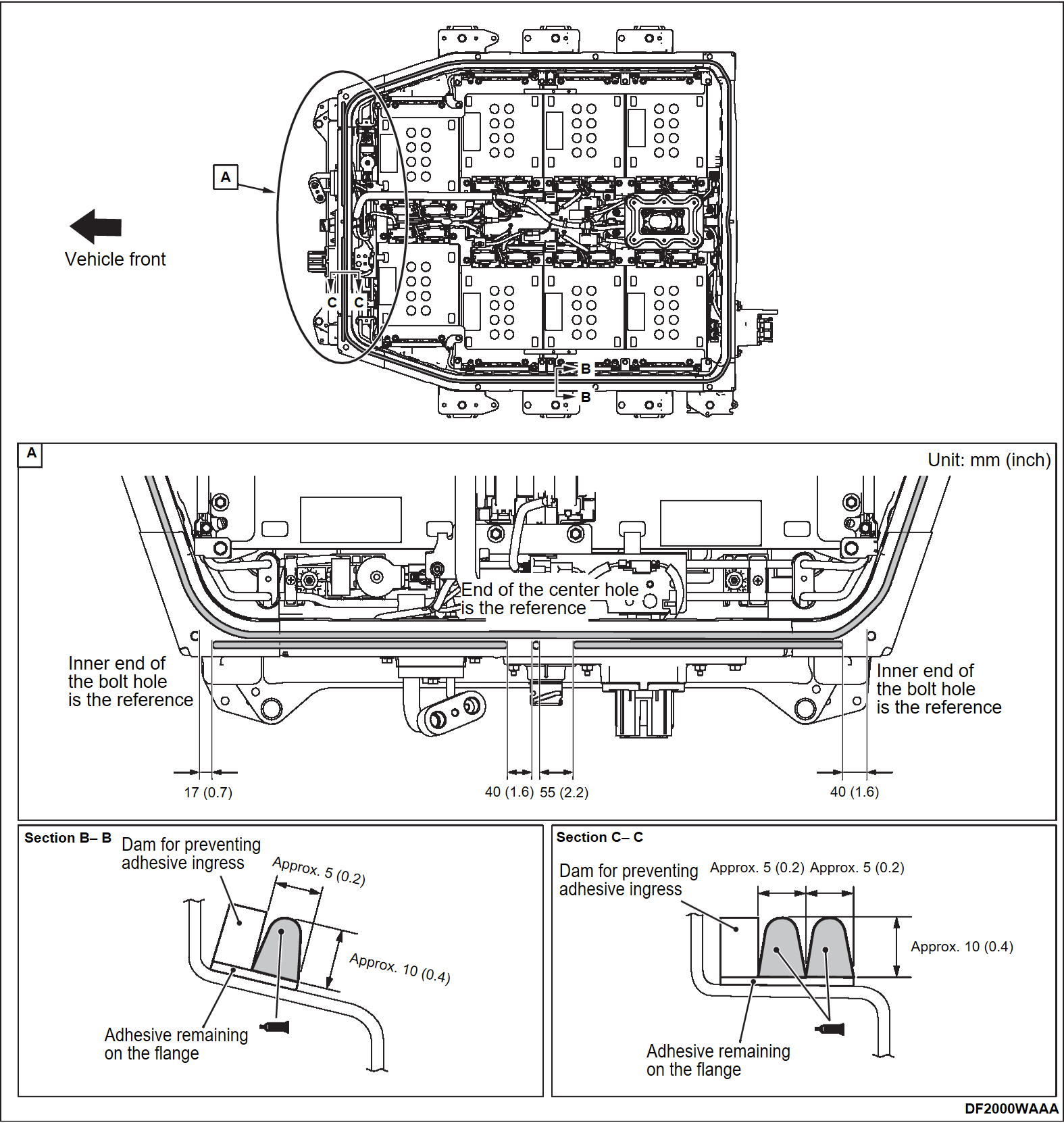
2. Attach the dam for preventing adhesive ingress all around the inside of the adhesive remaining on the battery tray flange so that there is no gaps.
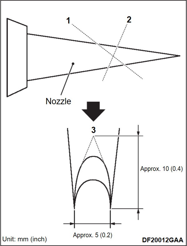
3. Cut the nozzle tip of the sealant gun in the following procedure.
- Cut the nozzle tip as showing in the illustration.
- Check whether the adhesive can be applied with the standard dimension [5 × 10 mm (0.2 × 0.4 inches)], and if it is less than standard, perform the cutting operation again.
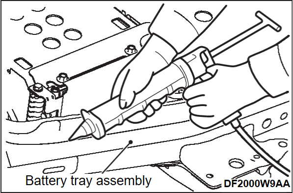
4. Use the sealant gun.
5.
| caution | After applying adhesive, make sure that the adhesive flow prevention dam has not fallen down toward the adhesive side. |
Apply adhesive YOKOHAMA RUBBER HAMATITE WS-272 or equivalent to the battery tray assembly as showing in the illustaration.
6.
| caution |
|
Install the battery tray cover while checking the hole positions of the battery tray and the battery tray cover.
7. Make sure that the mounting bolts of the battery tray cover is tightened to the specified torque.
Tightening torque of the ground bolts: 13 ± 1 N·m (115 ± 8 in-lb)
Tightening torque of the rest 4 mounting bolts: 7.0 ± 1.4 N·m (62 ± 12 in-lb)
8. Carried out the air leak check after install the battery tray cover (Refer to AIR LEAK CHECK ).
).
 ).
).![[Previous]](../../../buttons/fprev.png)
![[Next]](../../../buttons/fnext.png)
