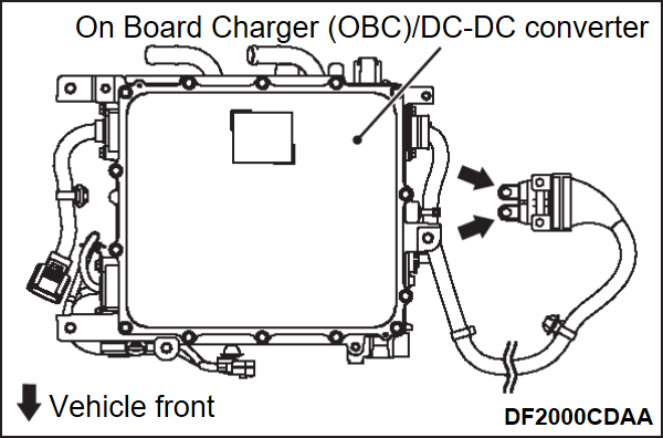
CHECK ON INSULATION RESISTANCE OF ON BOARD CHARGER (OBC)/DC-DC CONVERTER
| danger |
|
| caution | The insulation resistance check must be completed within 10 seconds. (Since DC 1,000 V is applied while checking, parts may be damaged if the check continues for 10 seconds or more.) |
Required Special Tools:
- MB991223: Wiring harness set
- MB992006: Extra fine probe
- MB992355: Electric insulation tester
1. Remove the third seat (Refer to Removal and Installation ).
).
 ).
).2. Remove the cargo floor cover (Refer to Removal and Installation ).
).
 ).
).3. Remove the EV control unit cover (LH/RH) (Refer to ON BOARD CHARGER (OBC) &DC-DC CONVERTER REMOVAL AND INSTALLATION ).
).
 ).
).4. Remove the junction box upper lid (Refer to JUNCTION BOX REMOVAL AND INSTALLATION ).
).
 ).
).5. Disconnect the On Board Charger (OBC)/DC-DC converter cable from the junction box (Refer to ON BOARD CHARGER (OBC) &DC-DC CONVERTER REMOVAL AND INSTALLATION ).
).
 ).
).6. Use the electric insulation tester (Special tool: MB992355) and set it to the 1,000 V range.
7. Measure the insulation resistance between the On Board Charger (OBC)/DC-DC converter high voltage terminals (P, N) and On Board Charger (OBC)/DC-DC converter (body ground).
Standard value: 10 MΩ or more
8. If the measured value is not within the standard value, replace the On Board Charger (OBC)/DC-DC converter.
![[Previous]](../../../buttons/fprev.png)
![[Next]](../../../buttons/fnext.png)
