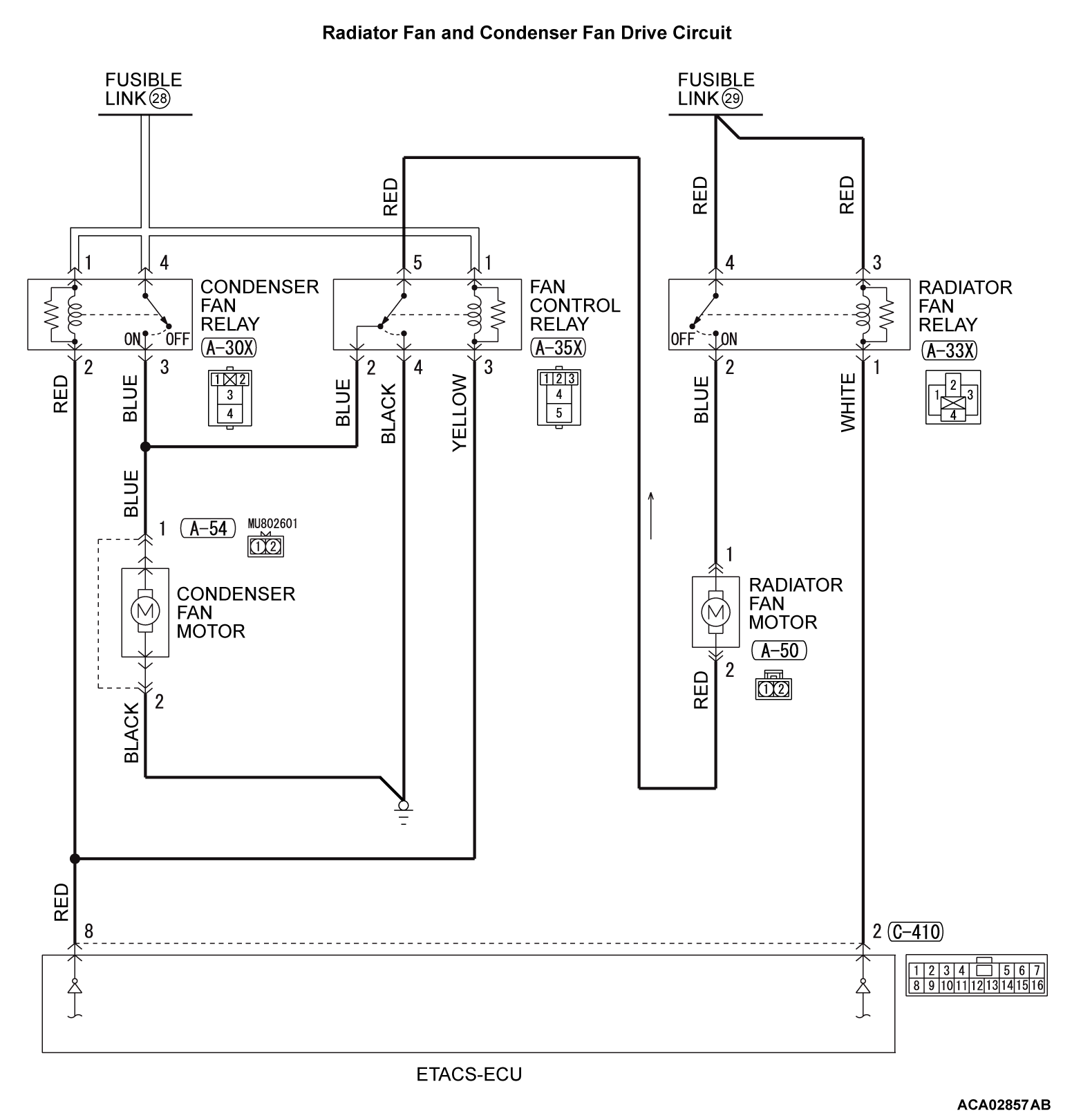
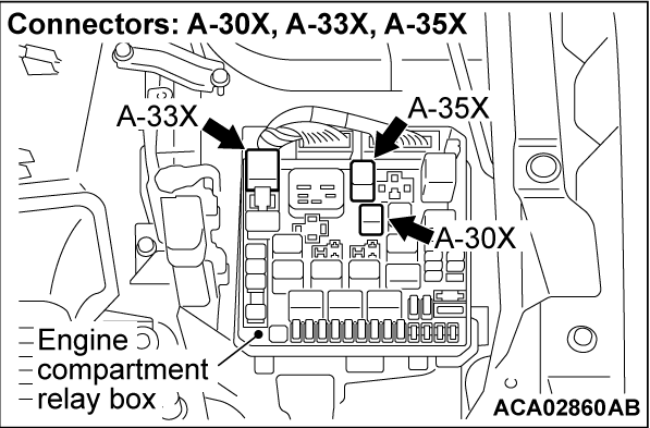
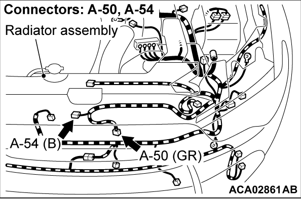
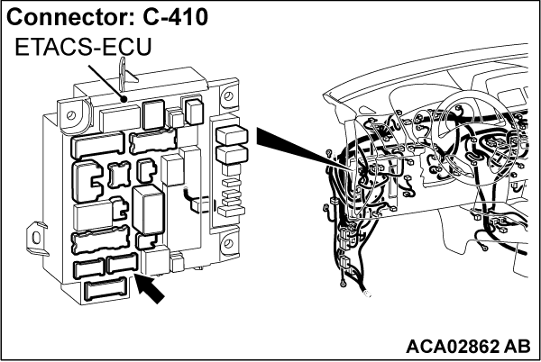
Inspection Procedure 3: Radiator Fan and Condenser Fan do not Operate (The Fans do not Operate or Operate Unintentionally).
CIRCUIT OPERATION
- Based on the signal from the engine coolant temperature sensor and the secondary pulley speed sensor signal (vehicle speed signal) from the transaxle control module (TCM), and the A/C switch signal from the A/C-ECU, the engine control module (ECM) sends the radiator fan and condenser fan control signal to the ETACS-ECU via CAN bus line.
- Based on the radiator fan and condenser fan control signal from the ECM, the ETACS-ECU turns ON/OFF the radiator fan relay, condenser fan relay, and the fan control relay to control the rotation of the radiator fan motor and condenser fan motor.
TECHNICAL DESCRIPTION
- If the radiator fan and condenser fan do not operate, the radiator fan motor, the condenser fan motor, the radiator fan relay, the condenser fan relay, the fan control relay, the ETACS-ECU may be defective.
- The CAN bus line, ETACS-ECU, CVT system, A/C system, or MFI system may also be defective.
TROUBLESHOOTING HINTS (THE MOST LIKELY CAUSES FOR THIS CASE:)
- Malfunction of CAN bus system.
- Damaged harness or connector.
- Malfunction of the MFI system.
- Malfunction of the CVT system.
- Malfunction of the A/C system.
- Malfunction of fusible link No. 28.
- Malfunction of fusible link No. 29.
- Malfunction of radiator fan relay.
- Malfunction of condenser fan relay.
- Malfunction of fan control relay.
- Malfunction of radiator fan motor.
- Malfunction of condenser fan motor.
- Malfunction of engine compartment relay box.
- Malfunction of ETACS-ECU.
- Malfunction of ECM.
DIAGNOSIS
STEP 1. Using scan tool MB991958, check the MFI system actuator test.
Using scan tool to check the MFI system actuator test (Refer to GROUP 13A, MFI Diagnosis - Diagnostic Function  ) <2.0L ENGINE> or (Refer to GROUP 13C, MFI Diagnosis - Diagnostic Function
  ) <2.4L ENGINE>.
 ) <2.0L ENGINE> or (Refer to GROUP 13C, MFI Diagnosis - Diagnostic Function
  ) <2.4L ENGINE>.
- Item 14: Cooling fan
Is the check result normal?
STEP 2. Using scan tool MB991958, read the MFI system DTC.
Using scan tool to read the MFI system DTC (Refer to GROUP 13A, MFI Diagnosis - Diagnostic Function  ) <2.0L ENGINE> or (Refer to GROUP 13C, MFI Diagnosis - Diagnostic Function
  ) <2.4L ENGINE>.
 ) <2.0L ENGINE> or (Refer to GROUP 13C, MFI Diagnosis - Diagnostic Function
  ) <2.4L ENGINE>.
Is any DTC set?
STEP 3. Using scan tool MB991958, read the CVT system DTC.
Using scan tool to read the CVT system DTC (Refer to GROUP 23A, Troubleshooting - Diagnosis Function  ).
).
 ).
).Is any DTC set?
STEP 4. Using scan tool MB991958, read the A/C system DTC.
Using scan tool to read the A/C system DTC (Refer to GROUP 55A, Manual A/C Diagnosis - Diagnosis Function  ) <vehicles with manual A/C> or (Refer to GROUP 55B, Automatic A/C Diagnosis - Diagnosis Function
  ) <vehicles with automatic A/C>.
 ) <vehicles with manual A/C> or (Refer to GROUP 55B, Automatic A/C Diagnosis - Diagnosis Function
  ) <vehicles with automatic A/C>.
Is any DTC set?
STEP 5. Using scan tool MB991958, read the ETACS system DTC.
Using scan tool to read the ETACS system DTC (Refer to GROUP 54A, ETACS, Troubleshooting - Diagnosis Function  ).
).
 ).
).Is any DTC set?
STEP 6. Check the radiator fan relay, the condenser fan relay and the fan control relay.
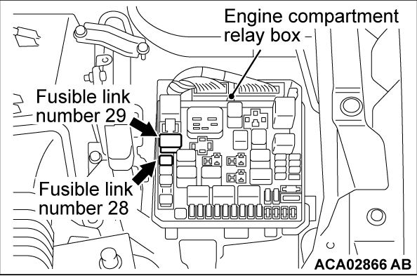
STEP 7. Check the fusible link number 28 and fusible link number 29.
STEP 8. Check the radiator fan motor and the condenser fan motor.
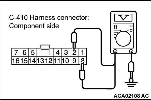
STEP 9. Measure the terminal voltage at ETACS-ECU connector C-410.
(1) Disconnect the ETACS-ECU connector C-410 and measure at the harness connector side.
(2) Turn the ignition switch to the "ON" position.
(3) Measure the terminal voltage between ETACS-ECU connector C-410 terminal number 2 and body ground, and between ETACS-ECU connector C-410 terminal number 8 and body ground.
OK: Battery positive voltage.
Is the check result normal?
STEP 10. Check the condenser fan relay connector A-30X, radiator fan relay connector A-33X, fan control relay connector A-35X, and ETACS-ECU connector C-410, for loose, corroded or damaged terminals, or terminals pushed back in the connector.
Refer to GROUP 00E, Harness Connector Inspection  .
. Repair or replace the damaged connectors or replace the relay box.
 .
.Are the connectors and terminals in good condition?
 Repair or replace the damaged connectors or replace the relay box.
STEP 11. Check the harness wire between fusible link number 28 and condenser fan relay connector A-30X terminal number 1, between fusible link number 28 and fan control relay connector A-35X terminal number 1, and between fusible link number 29 and radiator fan relay connector A-33X terminal number 3, for damage.
- Check harness wire for open/short circuit and damage.
Are the harness wires in good condition?
 Repair or replace the damaged harness wire or replace the relay box.
STEP 12. Check the harness wire between condenser fan relay connector A-30X terminal number 2 and ETACS-ECU connector C-410 terminal number 8, between radiator fan relay connector A-33X terminal number 1 and ETACS-ECU connector C-410 terminal number 2, and between fan control relay connector A-35X terminal number 3 and ETACS-ECU connector C-410 terminal number 8, for damage.
- Check harness wire for open/short circuit and damage.
Are the harness wires in good condition?
 Repair or replace the damaged harness wire.
STEP 13. Check the condenser fan relay connector A-30X, radiator fan relay connector A-33X, fan control relay connector A-35X, radiator fan motor connector A-50, and condenser fan motor connector A-54, for loose, corroded or damaged terminals, or terminals pushed back in the connector.
Refer to GROUP 00E, Harness Connector Inspection  .
. Repair or replace the damaged connectors or replace the relay box.
 .
.Are the connectors and terminals in good condition?
 Repair or replace the damaged connectors or replace the relay box.
STEP 14. Check the harness wire between fusible link number 28 and condenser fan relay connector A-30X terminal number 4, and between fusible link number 29 and radiator fan relay connector A-33X terminal number 4, for damage.
- Check harness wire for open/short circuit and damage.
Are the harness wires in good condition?
 Repair or replace the damaged harness wire or replace the relay box.
STEP 15. Check the harness wire between condenser fan relay connector A-30X terminal number 3 and condenser fan motor connector A-54 terminal number 1, and between radiator fan relay connector A-33X terminal number 2 and radiator fan motor connector A-50 terminal number 1, for damage.
- Check harness wire for open/short circuit and damage.
Are the harness wires in good condition?
 Repair or replace the damaged harness wire.
STEP 16. Check the harness wire between radiator fan motor connector A-50 terminal number 2 and fan control relay connector A-35X terminal number 5, and between condenser fan motor connector A-54 terminal number 2 and body ground, for damage.
- Check harness wire for open/short circuit and damage.
Are the harness wires in good condition?
 Repair or replace the damaged harness wire.
STEP 17. Check the harness wire between fan control relay connector A-35X terminal number 2 and condenser fan motor connector A-54 terminal number 1, and between fan control relay connector A-35X terminal number 4 and body ground, for damage.
- Check harness wire for open/short circuit and damage.
Are the harness wires in good condition?
 Repair or replace the damaged harness wire.
STEP 18. Using scan tool MB991958, read the ETACS system DTC.
Using scan tool to read the ETACS system DTC (Refer to GROUP 54A, ETACS, Troubleshooting - Diagnostic Function  ).
).
 ).
).Is any DTC set?
STEP 19. Using scan tool MB991958, check the MFI system data list.
Using scan tool to check the MFI system data list (Refer to GROUP 13A, MFI Diagnosis - Diagnostic Function  ) <2.0L ENGINE> or (Refer to GROUP 13C, MFI Diagnosis - Diagnostic Function
  ) <2.4L ENGINE>.
 ) <2.0L ENGINE> or (Refer to GROUP 13C, MFI Diagnosis - Diagnostic Function
  ) <2.4L ENGINE>.
- Item No. 6: Engine coolant temperature sensor
Is the check result normal?
STEP 20. Using scan tool MB991958, check the A/C system actuator test.
Using scan tool to check the MFI system actuator test (Refer to GROUP 55B, Automatic A/C Diagnosis - Diagnostic Function  ).
).
 ).
).- Item No. 10: Condenser fan
Is the check result normal?
![[Previous]](../../../buttons/fprev.png)
![[Next]](../../../buttons/fnext.png)
