DIAGNOSTIC FUNCTION
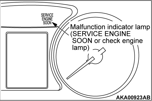
MALFUNCTION INDICATOR LAMP (SERVICE ENGINE SOON OR CHECK ENGINE LAMP)
Among the on-board diagnostic items, Malfunction Indicator Lamp (SERVICE ENGINE SOON or Check Engine Lamp) illuminates or blinks to notify the driver of an emission control malfunction.
However, when an irregular signal returns to normal and the engine control module judges that it has returned to normal, the Malfunction Indicator Lamp (SERVICE ENGINE SOON or Check Engine Lamp) will switch off.
When the ignition switch is in the ON position, the indicator lamp should be illuminated. When the engine starts, the indicator lamp should be extinguished.
| note | When the Transaxle Control Module (TCM) detects malfunctions related to the CVT, the Malfunction indicator Lamp (SERVICE ENGINE SOON or Check Engine Lamp) is also illuminated. |
Items Indicated by the Malfunction Indicator Lamp (SERVICE ENGINE SOON or Check Engine Lamp)
| DTC | ITEM |
| P0010 | Intake engine oil control valve circuit |
| P0011 | Intake variable valve timing system target error |
| P0013 | Exhaust engine oil control valve circuit |
| P0014 | Exhaust variable valve timing system target error |
| P0016 | Crankshaft/camshaft (intake) position sensor phase problem |
| P0017 | Crankshaft/camshaft (exhaust) position sensor phase problem |
| P0031 | Linear air-fuel ratio sensor heater control circuit low |
| P0032 | Linear air-fuel ratio sensor heater control circuit high |
| P0037 | Heated oxygen sensor (rear) heater control circuit low |
| P0038 | Heated oxygen sensor (rear) heater control circuit high |
| P0053 | Linear air-fuel ratio sensor heater resistance |
| P0068*1 | Mass airflow sensor plausibility |
| P0069 | Abnormal correlation between manifold absolute pressure sensor and barometric pressure sensor |
| P0102*1 | Mass airflow circuit low input |
| P0103*1 | Mass airflow circuit high input |
| P0106 | Manifold absolute pressure circuit range/performance problem |
| P0107 | Manifold absolute pressure circuit low input |
| P0108 | Manifold absolute pressure circuit high input |
| P0111*1 | Intake air temperature circuit range/performance problem |
| P0112*1 | Intake air temperature circuit low input |
| P0113*1 | Intake air temperature circuit high input |
| P0116*1 | Engine coolant temperature circuit range/performance problem |
| P0117*1 | Engine coolant temperature circuit low input |
| P0118*1 | Engine coolant temperature circuit high input |
| P011B | Engine coolant temperature /intake air temperature correlation |
| P0121*1 | Throttle position sensor (main) plausibility |
| P0122*1 | Throttle position sensor (main) circuit low input |
| P0123*1 | Throttle position sensor (main) circuit high input |
| P0125*1 | Insufficient coolant temperature for closed loop fuel control |
| P0128 | Coolant thermostat (coolant temperature below thermostat regulating temperature) |
| P0130 | Linear air-fuel ratio sensor circuit |
| P0131 | Linear air-fuel ratio sensor circuit low voltage |
| P0132 | Linear air-fuel ratio sensor circuit high voltage |
| P0133 | Linear air-fuel ratio sensor circuit slow response |
| P0134 | Linear air-fuel ratio sensor circuit no activity detected |
| P0137 | Heated oxygen sensor (rear) circuit low voltage |
| P0138 | Heated oxygen sensor (rear) circuit high voltage |
| P0139 | Heated oxygen sensor (rear) circuit slow response |
| P0140 | Heated oxygen sensor (rear) circuit no activity detected |
| P014C | Linear air-fuel ratio sensor circuit slow response - rich to lean |
| P014D | Linear air-fuel ratio sensor circuit slow response - lean to rich |
| P015A | Linear air-fuel ratio sensor circuit delayed response - rich to lean |
| P015B | Linear air-fuel ratio sensor circuit delayed response - lean to rich |
| P0171 | System too lean |
| P0172 | System too rich |
| P0181 | Fuel tank temperature sensor circuit range/performance |
| P0182 | Fuel tank temperature sensor circuit low input |
| P0183 | Fuel tank temperature sensor circuit high input |
| P0221*1 | Throttle position sensor (sub) plausibility |
| P0222*1 | Throttle position sensor (sub) circuit low input |
| P0223*1 | Throttle position sensor (sub) circuit high input |
| P0261 | Injector circuit low input - cylinder 1 |
| P0262 | Injector circuit high input - cylinder 1 |
| P0264 | Injector circuit low input - cylinder 2 |
| P0265 | Injector circuit high input - cylinder 2 |
| P0267 | Injector circuit low input - cylinder 3 |
| P0268 | Injector circuit high input - cylinder 3 |
| P0270 | Injector circuit low input - cylinder 4 |
| P0271 | Injector circuit high input - cylinder 4 |
| P0300*2 | Random/multiple cylinder misfire detected |
| P0301*2 | Cylinder 1 misfire detected |
| P0302*2 | Cylinder 2 misfire detected |
| P0303*2 | Cylinder 3 misfire detected |
| P0304*2 | Cylinder 4 misfire detected |
| P0327 | Knock sensor circuit low |
| P0328 | Knock sensor circuit high |
| P0335*1 | Crankshaft position sensor circuit |
| P0340*1 | Intake camshaft position sensor circuit |
| P0365 | Exhaust camshaft position sensor circuit |
| P0400 | Exhaust gas recirculation system |
| P0420 | Warm up catalyst efficiency below threshold |
| P0441 | Evaporative emission control system incorrect purge flow |
| P0442 | Evaporative emission control system leak detected (small leak) |
| P0450 | Evaporative emission control system pressure sensor malfunction |
| P0451 | Evaporative emission control system pressure sensor range/performance |
| P0452 | Evaporative emission control system pressure sensor low input |
| P0453 | Evaporative emission control system pressure sensor high input |
| P0455 | Evaporative emission control system leak detected (gross leak) |
| P0456 | Evaporative emission control system leak detected (very small leak) |
| P0458 | Evaporative emission control system purge control valve circuit low input |
| P0459 | Evaporative emission control system purge control valve circuit high input |
| P0461 | Fuel level sensor <FWD> or fuel level sensor (main) <AWD> circuit range/performance |
| P0462 | Fuel level sensor <FWD> or fuel level sensor (main) <AWD> circuit low input |
| P0463 | Fuel level sensor <FWD> or fuel level sensor (main) <AWD> circuit high input |
| P0489 | EGR valve (stepper motor) circuit malfunction (ground short) |
| P0490 | EGR valve (stepper motor) circuit malfunction (battery short) |
| P0498 | Evaporative emission control system ventilation control valve circuit low input |
| P0499 | Evaporative emission control system ventilation control valve circuit high input |
| P0506 | Idle control system RPM lower than expected |
| P0507 | Idle control system RPM higher than expected |
| P050A | Cold start idle air control system performance |
| P050B | Ignition timing retard insufficient |
| P0602*1 | Control module programming error |
| P0604*1 | Internal control module random access memory (RAM) error |
| P0606*1 | Engine control module main processor malfunction |
| P060B*1 | Internal control module A/D processing performance problem |
| P060D*1 | Internal control module accelerator pedal position performance problem |
| P061A*1 | Internal control module torque performance problem |
| P061C*1 | Internal control module engine RPM performance problem |
| P062F*1 | Internal control module EEPROM error |
| P0630*1 | Vehicle Identification Number (VIN) malfunction |
| P0638*1 | Throttle actuator control motor circuit range/ performance |
| P0642*1 | Throttle position sensor power supply |
| P0657*1 | Throttle actuator control motor relay circuit malfunction |
| P1238*1 | Mass airflow sensor plausibility (torque monitor) |
| P1590*1 | TCM to ECM communication error in torque reduction request |
| P1603*1 | Battery backup circuit malfunction |
| P2066 | Fuel level sensor (sub) circuit range/performance <AWD> |
| P2096 | Post catalyst fuel trim system too lean |
| P2097 | Post catalyst fuel trim system too rich |
| P2100*1 | Throttle actuator control motor circuit (open) |
| P2101*1 | Throttle actuator control motor magneto malfunction |
| P2122*1 | Accelerator pedal position sensor (main) circuit low input |
| P2123*1 | Accelerator pedal position sensor (main) circuit high input |
| P2127*1 | Accelerator pedal position sensor (sub) circuit low input |
| P2128*1 | Accelerator pedal position sensor (sub) circuit high input |
| P2135*1 | Throttle position sensor (main and sub) range/performance problem |
| P2138*1 | Accelerator pedal position sensor (main and sub) range/performance problem |
| P2228*1 | Barometric pressure circuit low input |
| P2229*1 | Barometric pressure circuit high input |
| P2237 | Linear air-fuel ratio sensor positive current control circuit/open |
| P2243 | Linear air-fuel ratio sensor reference voltage circuit/open |
| P2251 | Linear air-fuel ratio sensor negative current control circuit/open |
| P2252 | Heated oxygen sensor offset circuit low voltage |
| P2253 | Heated oxygen sensor offset circuit high voltage |
| U0101*1 | TCM time-out |
| U0141*1 | ETACS-ECU time-out |
| U1180*1 | Combination meter time-out |
| note | If the Malfunction Indicator Lamp (SERVICE ENGINE SOON or Check Engine Lamp) illuminates because of a malfunction of the engine control module (ECM), communication between the scan tool MB991958 (M.U.T.-III sub assembly) and the ECM is impossible. In this case, the diagnostic trouble code cannot be read. |
| note | After the ECM has detected a malfunction, the Malfunction Indicator Lamp (SERVICE ENGINE SOON or Check Engine Lamp) illuminates when the engine is next turned on and the same malfunction is re-detected. However, for items marked with a "*1" in the DTC NO. column, the Malfunction Indicator Lamp (SERVICE ENGINE SOON or Check Engine Lamp) illuminates only on the first detection of the malfunction. |
| note | The codes marked with a "*2" in the diagnostic trouble code number column have the following two conditions for illuminating the Malfunction Indicator Lamp (SERVICE ENGINE SOON or Check Engine Lamp). |
- In case that the misfire causing the damaged catalyst is detected, the Malfunction Indicator Lamp (SERVICE ENGINE SOON or Check Engine Lamp) will flash until the condition is corrected. If the system detects the same malfunction after the next engine start and then the condition is corrected, the Malfunction Indicator Lamp (SERVICE ENGINE SOON or Check Engine Lamp) will flash (not illuminate).
- In case that the misfire deteriorating the exhaust gas is detected, the Malfunction Indicator Lamp (SERVICE ENGINE SOON or Check Engine Lamp) is illuminated when the same malfunction is redetected after the next engine start.
| note | Even if the malfunction is not detected when the ECM monitors the malfunction three consecutive times* after the Malfunction Indicator Lamp (SERVICE ENGINE SOON or Check Engine Lamp) illuminates, turn off the Malfunction Indicator Lamp (SERVICE ENGINE SOON or Check Engine Lamp) when the engine starts next time.
|
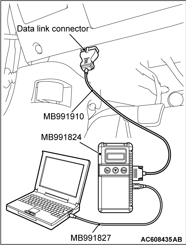
HOW TO CONNECT THE SCAN TOOL (M.U.T.-III)
Required Special Tool:
- MB991958: Scan Tool (M.U.T.-III Sub Assembly)
- MB991824: V.C.I.
- MB991827: USB Cable
- MB991910: Main Harness A
| caution | To prevent damage to scan tool MB991958, always turn the ignition switch to the "LOCK" (OFF) position before connecting or disconnecting scan tool MB991958. |
1. Ensure that the ignition switch is at the "LOCK" (OFF) position.
2. Start up the personal computer.
3. Connect special tool MB991827 to special tool MB991824 and the personal computer.
4. Connect special tool MB991910 to special tool MB991824.
5. Connect special tool MB991910 to the data link connector.
6. Turn the power switch of special tool MB991824 to the "ON" position.
| note | When the special tool MB991824 is energized, special tool MB991824 indicator light will be illuminated in a green color. |
7. Start the M.U.T.-III system on the personal computer.
| note | Disconnecting the scan tool MB991958 is the reverse of the connecting sequence, making sure that the ignition switch is at the "LOCK" (OFF) position. |
HOW TO READ AND ERASE DIAGNOSTIC TROUBLE CODES.
Required Special Tool:
- MB991958: Scan Tool (M.U.T.-III Sub Assembly)
- MB991824: V.C.I.
- MB991827: USB Cable
- MB991910: Main Harness A
| caution | To prevent damage to scan tool MB991958, always turn the ignition switch to the "LOCK" (OFF) position before connecting or disconnecting scan tool MB991958. |
| note | If the diagnostic trouble code (DTC) of the transaxle control module (TCM) had been erased, the DTC of the engine control module (ECM) had also been erased at the same time. |
1. Connect scan tool MB991958 to the data link connector.
2. Turn the ignition switch to the "ON" position.
3. Select "System select."
4. Choose "from 2006 MY" under "MODEL YEAR".
5. Check that "Vehicle Information" contents are correct.
6. Choose "MFI".
7. Select "Diagnostic Trouble Code"
8. If a DTC is set, it is shown.
9. Choose "Erase DTCs" to erase the DTC.
HOW TO READ DATA LIST
Required Special Tool:
- MB991958: Scan Tool (M.U.T.-III Sub Assembly)
- MB991824: V.C.I.
- MB991827: USB Cable
- MB991910: Main Harness A
| caution | To prevent damage to scan tool MB991958, always turn the ignition switch to the "LOCK" (OFF) position before connecting or disconnecting scan tool MB991958. |
1. Connect scan tool MB991958 to the data link connector.
2. Turn the ignition switch to the "ON" position.
3. Select "System select."
4. Choose "from 2006 MY" under "MODEL YEAR".
5. Check that "Vehicle Information" contents are correct.
6. Choose "MFI".
7. Select "Data List."
8. Choose an appropriate item and select the "OK" button.
HOW TO PERFORM ACTUATOR TEST
Required Special Tool:
- MB991958: Scan Tool (M.U.T.-III Sub Assembly)
- MB991824: V.C.I.
- MB991827: USB Cable
- MB991910: Main Harness A
| caution | To prevent damage to scan tool MB991958, always turn the ignition switch to the "LOCK" (OFF) position before connecting or disconnecting scan tool MB991958. |
1. Connect scan tool MB991958 to the data link connector.
2. Turn the ignition switch to the "ON" position.
3. Select "System select."
4. Choose "from 2006 MY" under "MODEL YEAR".
5. Check that "Vehicle Information" contents are correct.
6. Choose "MFI".
7. Select "Actuator Test."
8. Choose an appropriate item and select the "OK" button.
HOW TO READ PROVISIONAL DIAGNOSTIC TROUBLE CODES
Required Special Tools:
- MB991958: Scan Tool (M.U.T.-III Sub Assembly)
- MB991824: V.C.I.
- MB991827: USB Cable
- MB991910: Main Harness A
If detecting the malfunction during the first drive cycle, the ECM temporarily sets the diagnostic trouble code as the provisional diagnostic trouble code. If detecting the same malfunction during the next drive cycle, the ECM determines that the malfunction exists. The ECM sets the diagnostic trouble code. On Scan Tool MB991958, it is possible to display the set provisional diagnostic trouble code which the ECM had detected during the first drive cycle. This makes it possible to confirm in one drive cycle whether the malfunction could happen again after the repair.
CONFIRMATION METHOD
| caution | To prevent damage to scan tool MB991958, always turn the ignition switch to the "LOCK" (OFF) position before connecting or disconnecting scan tool MB991958. |
1. Connect scan tool MB991958 to the data link connector.
2. Turn the ignition switch to the "ON" position.
3. Select "System select."
4. Choose "from 2006 MY" under "MODEL YEAR".
5. Check that "Vehicle Information" contents are correct.
6. Choose "MFI".
7. Select "Special Function" from MFI Screen.
8. Select "Provisional DTCs" from Special Function Screen.
PERMANENT DTC
The permanent DTC (PDTC) is stored in the EEPROM of the engine control module (ECM) as the permanent status, which checks that the malfunction of the emission related components/ the system has not been repaired yet. When detecting the malfunction necessary to illuminate the malfunction indicator lamp (SERVICE ENGINE SOON or Check Engine Lamp), the ECM illuminates the MIL and sets the appropriate DTC as the permanent DTC in the EEPROM concurrently. The usual DTC is stored in the EEPROM aside from this. The ECM can store up to 6 PDTCs. The ECM, therefore, cannot store the 7th and subsequent PDTCs. If the temporary malfunction causes the malfunction indicator lamp to be illuminated and then the reinstatement during the subsequent driving causes it to be extinguished, the PDTC is erased. Also if the ECM checks that the DTC malfunction is fixed during the driving after the DTC repair is completed, the PDTC is erased. The permanent DTC, however, is not erased by disconnecting the battery terminal or erasing with the scan tool (M.U.T-III). The permanent DTC can be erased if all readiness statuses are erased or not completed at the time of reprogramming the ECM. If must be erased while the vehicle is repaired, the PDTC can be erased by the procedures shown below. If must be erased because of the failure to pass the Inspection and Maintenance (I/M) test, the permanent DTC can also be erased by the following procedure:
PROCEDURES FOR ERASING PERMANENT DTC
1. Check that the DTC is not set. If the DTC is set, perform the DTC troubleshooting, then repair the DTC.
| note | The order of Step 2 and 3 can be exchanged. |
2. Drive the vehicle at least once under the conditions satisfying all the following requirements:
- The total driving (engine running) time must be more than 10 consecutive minutes.
- More than 30 consecutive seconds of idling must be included in the driving
- More than 5 accumulated minutes of driving at more than 40 km/h (25 mph) must be included in the driving.
| note | Select MODE 0A from scan tool and check Item 1: PDTC clear condition current D/C. When the driving conditions are satisfied, "satisfied" should be displayed. |
3. Drive the vehicle at least two times in the drive cycle pattern suitable for the permanent DTC. (Refer to OBD-II DRIVE CYCLE for the drive cycle pattern.) If the DTC does not have the drive cycle pattern, start and stop the engine. Wait 15 seconds or more to start again after the stop. Repeat at least 2 times.
4. Restart and stop the engine.
5. Check that the permanent DTC is erased. If the permanent DTC is not erased, check the DTC or the provisional DTC. If the malfunction code is set, repair the DTC. Try to erase the permanent DTC again (from Step 1 to 5). If the malfunction code is not set, the drive cycle pattern (Step 3) monitoring the malfunction can possibly be insufficient.
MODE 6 REFERENCE TABLE
The engine control module (ECM) monitors the condition of emission control system. By selecting MODE 6 using scan tool, Test Result and Limit Value (minimum) *1 or (maximum) *2 about the main items of emission control system which ECM monitors can be confirmed. The value at the last monitoring is output by ECM as a test result.| ON-BOARD DIAGNOSTIC MONITOR ID | STANDARDIZED / MANUFACTURER DEFINED TEST ID | MONITORING ITEM | SIMPLE TECHNICAL DESCRIPTION | CONVERSION COEFFICIENT IN USING GENERAL SCAN TOOL |
| 01 | 81 | WR-HO2S Monitor Bank 1 - Sensor 1 Rich/Lean Switching frequency | ECM monitors the deteriorated condition of the linear air-fuel ratio sensor by checking the rich/lean switching frequency of the linear air-fuel ratio sensor. | × 1 count |
| 94 | WR-HO2S Monitor Bank 1 - Sensor 1 Lean to Rich Slow Response | ECM checks the rich/lean ratio of the linear air-fuel ratio sensor in order to monitor the response of the linear air-fuel ratio sensor. | × 0.00390625 Ratio | |
| 95 | WR-HO2S Monitor Bank 1 - Sensor 1 Rich to Lean Slow Response | ECM checks the lean/rich ratio of the linear air-fuel ratio sensor in order to monitor the response of the linear air-fuel ratio sensor. | × 0.00390625 Ratio | |
| 96 | WR-HO2S Monitor Bank 1 - Sensor 1 Lean to Rich Delay | ECM checks the lean to rich delay time of the linear air-fuel ratio sensor in order to monitor the response of the linear air-fuel ratio sensor. | × 1 msec | |
| 97 | WR-HO2S Monitor Bank 1 - Sensor 1 Rich to Lean Delay | ECM checks the rich to lean delay time of the linear air-fuel ratio sensor in order to monitor the response of the linear air-fuel ratio sensor. | × 1 msec | |
| 9B | WR-HO2S Monitor Bank 1 - Sensor 1 Target Air-Fuel Adjustment Value for Lean to Rich Slow Response | ECM checks the target air-fuel adjustment value in order to monitor the response of the linear air-fuel ratio sensor. | × 0.003052% | |
| 9C | WR-HO2S Monitor Bank 1 - Sensor 1 Target Air-Fuel Adjustment Value for Rich to Lean Slow Response | ECM checks the target air-fuel adjustment value in order to monitor the response of the linear air-fuel ratio sensor. | × 0.003052% | |
| 9D | WR-HO2S Monitor Bank 1 - Sensor 1 Target Air-Fuel Adjustment Value for Lean to Rich Delay | ECM checks the target air-fuel adjustment value in order to monitor the response of the linear air-fuel ratio sensor. | × 0.003052% | |
| 9E | WR-HO2S Monitor Bank 1 - Sensor 1 Target Air-Fuel Adjustment Value for Rich to Lean Delay | ECM checks the target air-fuel adjustment value in order to monitor the response of the linear air-fuel ratio sensor. | × 0.003052% | |
| 02 | 08 | Oxygen Sensor Monitor Bank 1 - Sensor 2 Maximum Sensor Voltage for Test Cycle | ECM checks the output voltage of the heated oxygen sensor (rear) in order to monitor whether the heated oxygen sensor (rear) outputs the rich signal. | × 0.122mV |
| 82 | Oxygen Sensor Monitor Bank 1 - Sensor 2 Output Voltage change | ECM checks the output voltage of the heated oxygen sensor (rear) in order to monitor whether the heated oxygen sensor (rear) output is stuck. | × 0.122 mV | |
| 88 | Oxygen Sensor Monitor Bank 1 - Sensor 2 Output Voltage drop slope | ECM checks the output voltage drop slope of the heated oxygen sensor (rear) in order to monitor the response of the heated oxygen sensor (rear). | × 1 msec | |
| 98 | Oxygen Sensor Monitor Bank 1 - Sensor 2 Rich To Lean Sensor Switch Air Quantity | ECM checks the rich to lean switching air quantity of the heated oxygen sensor (rear) in order to monitor the response of the heated oxygen sensor (rear). | × 0.01 g | |
| 21 | 83 | Catalyst Monitor Bank 1 Frequency ratio between Front- and Rear-Oxygen Sensors | ECM monitors the deterioration of catalyst by the output frequency ratio between linear air-fuel ratio sensor and heated oxygen sensor (rear). | × 0.0039 |
| 31 | 84 | EGR Monitor Difference of manifold pressure before and after EGR activation for Insufficient detected | ECM monitors the operation of EGR system by the pressure difference of intake manifold between before and after introduction of EGR using the manifold absolute pressure sensor. | × 0.0117 kPa |
| 35 | 89 | VVT Monitor Bank 1 (L4-IN) Cam Phase Angle Deviation (between target and actual position) | ECM monitors the deviation between the intake camshaft target phase angle and the intake camshaft actual phase angle. | × 0.01° |
| 36 | 89 | VVT Monitor Bank 2 (L4-EX) Cam Phase Angle Deviation (between target and actual position) | ECM monitors the deviation between the exhaust camshaft target phase angle and the exhaust camshaft actual phase angle. | × 0.01° |
| 39 | 85 | EVAP Monitor (Cap off) Pressure drop during de-pressurizing | ECM monitors the leak of fuel evaporation gas by checking whether the pressure can be reduced (the amount of pressure reduction) using the fuel tank differential pressure sensor after sealing the fuel tank and the fuel line. | × 0.01 kPa |
| 3B | 85 | EVAP Monitor (0.040") Pressure rise during airtight condition | After ECM vacuumizes the fuel tank and the fuel line and then the specified time is passed, ECM monitors the leak of fuel evaporation gas through the fuel tank differential pressure sensor to check the reduction of vacuum in the fuel tank. | × 0.0117 kPa |
| 3C | 85 | EVAP Monitor (0.020") Pressure rise during airtight condition | After ECM vacuumizes the fuel tank and the fuel line and then the specified time is passed, ECM monitors the leak of fuel evaporation gas through the fuel tank differential pressure sensor to check the reduction of vacuum in the fuel tank. | × 0.0117 kPa |
| 41 | 86 | WR-HO2S Heater Monitor Bank1 - Sensor1 Heater Monitoring Current | ECM checks the amperage of the linear air-fuel ratio sensor heater. | × 0.001 A |
| A2 | 0B | Mis-Fire Cylinder 1 Data EWMA Misfire Counts For Last 10 Driving Cycles | ECM monitors angular acceleration of crankshaft and detect misfire. EWMA (Exponential Weighted Moving Average) misfire counts for last 10 driving cycles. | × 1 count |
| 0C | Mis-Fire Cylinder 1 Data Misfire Counts For Last/Current Driving Cycle | ECM monitors angular acceleration of crankshaft and detect misfire. Misfire counts for last/current driving cycle. | × 1 count | |
| A3 | 0B | Mis-Fire Cylinder 2 Data EWMA Misfire Counts For Last 10 Driving Cycles | ECM monitors angular acceleration of crankshaft and detect misfire. EWMA (Exponential Weighted Moving Average) misfire counts for last 10 driving cycles. | × 1 count |
| 0C | Mis-Fire Cylinder 2 Data Misfire Counts For Last/Current Driving Cycle | ECM monitors angular acceleration of crankshaft and detect misfire. Misfire counts for last/current driving cycle. | × 1 count | |
| A4 | 0B | Mis-Fire Cylinder 3 Data EWMA Misfire Counts For Last 10 Driving Cycles | ECM monitors angular acceleration of crankshaft and detect misfire. EWMA (Exponential Weighted Moving Average) misfire counts for last 10 driving cycles. | × 1 count |
| 0C | Mis-Fire Cylinder 3 Data Misfire Counts For Last/Current Driving Cycle | ECM monitors angular acceleration of crankshaft and detect misfire. Misfire counts for last/current driving cycle. | × 1 count | |
| A5 | 0B | Mis-Fire Cylinder 4 Data EWMA Misfire Counts For Last 10 Driving Cycles | ECM monitors angular acceleration of crankshaft and detect misfire. EWMA (Exponential Weighted Moving Average) misfire counts for last 10 driving cycles. | × 1 count |
| 0C | Mis-Fire Cylinder 4 Data Misfire Counts For Last/Current Driving Cycle | ECM monitors angular acceleration of crankshaft and detect misfire. Misfire counts for last/current driving cycle. | × 1 count |
| note | *1: Minimum value: The test fails if test value is less than this value. |
| note | *2: Maximum value: The test fails if test value is greater than this value. |
| note | When not finishing the monitor of the driving cycle for the request of On-Board Monitoring Test Request, the ECM outputs the stored latest monitor test result. |
| note | When the monitored test results are erased by the battery disconnection and so on, the ECM outputs the values in hexadecimal of "0000" or "FFFF", otherwise it outputs abnormal values and so on. In case of this, the ECU outputs are handled as invalid-values. When the first monitor (Readiness Status) is completed after this, the ECM outputs the valid-values. |
| note | "Test Limit Type & Component ID byte" output from the ECM is given in hexadecimal of "00" or "80". "00" means the maximum value and "80" means the minimum value. |
ON-BOARD DIAGNOSTICS
The engine control module (ECM) monitors the input/output signals (some signals all the time and others under specified conditions) of the ECM. When a malfunction continues for a specified time or longer after the irregular signal is initially monitored, the ECM judges that a malfunction has occurred. After the ECM first detects a malfunction, a diagnostic trouble code is recorded when the engine is restarted and the same malfunction is re-detected. However, for items marked with a "*1", a diagnostic trouble code is recorded on the first detection of the malfunction. There are 138 diagnostic items. The diagnostic results can be read out with a scan tool. Since memorization of the diagnostic trouble codes is backed up directly by the battery, the diagnostic results are memorized even if the ignition key is turned off. The diagnostic trouble codes will, however, be erased when the battery terminal or the ECM connector is disconnected. In addition, the diagnostic trouble code can also be erased by turning the ignition switch to ON and sending the diagnostic trouble code erase signal from scan tool MB991958 to the ECM.
| note | If the sensor connector is disconnected with the ignition switch turned on, the diagnostic trouble code is memorized. In this case, send the diagnostic trouble code erase signal to the ECM in order to erase the diagnostic memory. The 138 diagnostic items are all indicated sequentially from the smallest code number. The ECM records the engine operating condition when the diagnostic trouble code is set. This data is called "Freeze-frame" data. This data can be read by using the scan tool, and can then be used in simulation tests for troubleshooting. Data items are as follows: |
| note | If the ECM detects multiple malfunctions, the ECM stores the "Freeze-frame" data for only the first item that was detected. However, if the ECM detects a misfire or a fuel system malfunction, the ECM stores the data by giving priority to the misfire or fuel system malfunction, regardless of the order in which the malfunction was detected. |
| note | As for Diagnostic trouble code P1603, "Freeze-frame" data is not memorized. |
Freeze Frame Data for M.U.T.-III
| ITEM NO. | M.U.T.-III SCAN TOOL DISPLAY | DATA ITEM | UNIT or STATE |
| 1 | Odometer | Odometer | km or mile |
| 2 | Ignition cycle (Warm up cycle) | Ignition cycle (Warm up cycle) | - |
| 4 | Accumulated minute | Accumulated minute* | min |
| note | *: Accumulated time of current malfunction from time point when malfunction is detected. |
Freeze Frame Data (OBD) for M.U.T.-III
| ITEM NO. | M.U.T.-III SCAN TOOL DISPLAY | DATA ITEM | UNIT or STATE |
| AA | Airflow sensor | Mass airflow sensor | g/s |
| AB | TP sensor (main) | Throttle position sensor (main) | % |
| BA | Target EGR | Target EGR stepper motor | % |
| BB | Barometric pressure sensor | Barometric pressure sensor | kPa or in.Hg |
| BC | Relative TP sensor | Relative throttle position sensor | % |
| BD | TP sensor (sub) | Throttle position sensor (sub) | % |
| BE | APP sensor (main) | Accelerator pedal position sensor (main) | % |
| BF | APP sensor (sub) | Accelerator pedal position sensor (sub) | % |
| C0 | Fuel system status (bank1) | Fuel control system status | Data items are displayed on scan tool display, but this item is not applicable. |
| C1* | Fuel system status (bank 2) | Fuel control system status (bank 2) | N/A |
| C2 | Calculated load value | Calculated load value | % |
| C3 | ECT sensor | Engine coolant temperature sensor | °C or °F |
| C4 | Short term fuel trim (bank 1) | Short-term fuel trim | % |
| C6 | Long term fuel trim (bank 1) | Long-term fuel trim | % |
| CC | MAP sensor | Manifold absolute pressure sensor | kPa or in.Hg |
| CD | Crankshaft position sensor | Crankshaft position sensor | r/min |
| CE | Vehicle speed | Vehicle speed | km/h or mph |
| CF | Spark advance | Spark advance | °CA |
| D0 | Intake air temperature sensor 1 | Intake air temperature sensor | °C or °F |
| D1 | Time since engine running | Time since engine running | sec |
| D6 | EVAP. emission purge SOL. duty | Evaporative emission purge solenoid duty | % |
| D7 | Fuel level gauge | Fuel level gauge | % |
| D8 | Power supply voltage | Power supply voltage | V |
| D9 | Absolute load value | Absolute load value | % |
| DA | Target equivalence ratio | Target equivalence ratio | - |
| DB | Intake air temperature sensor 1 | Intake air temperature sensor (ambient air temperature) | °C or °F |
| DC | Throttle actuator | Throttle actuator control motor | % |
| DD | Relative APP sensor | Relative accelerator pedal position sensor | % |
| 242 | Fuel tank differential PRS.SNSR | Fuel tank differential pressure sensor | Pa |
| 300 | Fuel system status A:OL | Fuel control system status: Open loop | Yes or No |
| 301 | Fuel system status A:CL | Fuel control system status: Closed loop | Yes or No |
| 302 | Fuel system status A:OL-Drive | Fuel control system status: Open loop-drive condition | Yes or No |
| 303 | Fuel system status A:OL-Fault | Fuel control system status: Open loop-DTC set | Yes or No |
| 304 | Fuel system status A:CL-Fault | Fuel control system status: Closed loop-heated oxygen sensor (rear) failed | Yes or No |
| 305* | Fuel system status A:OL B2 | Fuel control system status: Open loop (bank2) | No |
| 306* | Fuel system status A:OL-Drive B2 | Fuel control system status: Open loop-drive condition (bank2) | No |
| 307* | Fuel system status A:OL-Fault B2 | Fuel control system status: Open loop-DTC set (bank2) | No |
| 308* | Fuel system status B:OL | Fuel control system status B: Open loop | No |
| 309* | Fuel system status B:CL | Fuel control system status B: Closed loop | No |
| 310* | Fuel system status B:OL-Drive | Fuel control system status B: Open loop-drive condition | No |
| 311* | Fuel system status B:OL-Fault | Fuel control system status B: Open loop-DTC set | No |
| 312* | Fuel system status B:CL-Fault | Fuel control system status B: Closed loop-heated oxygen sensor (rear) failed | No |
| 313* | Fuel system status B:OL B2 | Fuel control system status B: Open loop (bank2) | No |
| 314* | Fuel system status B:OL-Drive B2 | Fuel control system status B: Open loop-drive condition (bank2) | No |
| 315* | Fuel system status B:OL-Fault B2 | Fuel control system status B: Open loop-DTC set (bank2) | No |
| note | *: Data items are displayed on scan tool display, but this item is not applicable and its data is always displayed as "N/A" or "No". |
Freeze Frame Data for General Scan Tool
| COMMON EXAMPLE of GENERAL SCAN TOOL DISPLAY | PARAMETER IDENTIFICATION (PID) | DESCRIPTION | UNIT or STATE |
| DTCFRZF | 02 | DTC that caused required freeze frame data storage | Pxxxx, Uxxxx |
| FUELSYS A | 03 | See M.U.T.-III Item No. 300 to 304 | |
| LOAD_PCT | 04 | See M.U.T.-III Item No. C2 | |
| ECT | 05 | See M.U.T.-III Item No. C3 | |
| SHRTFT 1 | 06 | See M.U.T.-III Item No. C4 | |
| LONGFT 1 | 07 | See M.U.T.-III Item No. C6 | |
| MAP | 0B | See M.U.T.-III Item No. CC | |
| RPM | 0C | See M.U.T.-III Item No. CD | |
| VSS | 0D | See M.U.T.-III Item No. CE | |
| SPARKADV | 0E | See M.U.T.-III Item No. CF | |
| IAT | 0F | See M.U.T.-III Item No. D0 | |
| MAF | 10 | See M.U.T.-III Item No. AA | |
| TP | 11 | See M.U.T.-III Item No. AB | |
| RUNTM | 1F | See M.U.T.-III Item No. D1 | |
| EGR_PCT | 2C | See M.U.T.-III Item No. BA | |
| EVAP_PCT | 2E | See M.U.T.-III Item No. D6 | |
| FLI | 2F | See M.U.T.-III Item No. D7 | |
| EVAP_VP | 32 | See M.U.T.-III Item No. 242 | |
| BARO | 33 | See M.U.T.-III Item No. BB | |
| VPWR | 42 | See M.U.T.-III Item No. D8 | |
| LOAD_ABS | 43 | See M.U.T.-III Item No. D9 | |
| EQ_RAT | 44 | See M.U.T.-III Item No. DA | |
| TP_R | 45 | See M.U.T.-III Item No. BC | |
| AAT | 46 | See M.U.T.-III Item No. DB | |
| TP_B | 47 | See M.U.T.-III Item No. BD | |
| APP_D | 49 | See M.U.T.-III Item No. BE | |
| APP_E | 4A | See M.U.T.-III Item No. BF | |
| TAC_PCT | 4C | See M.U.T.-III Item No. DC | |
| APP_R | 5A | See M.U.T.-III Item No. DD | |
OBD- II DRIVE CYCLE
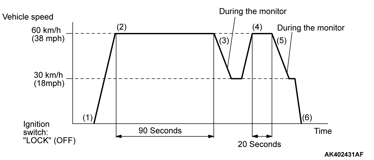
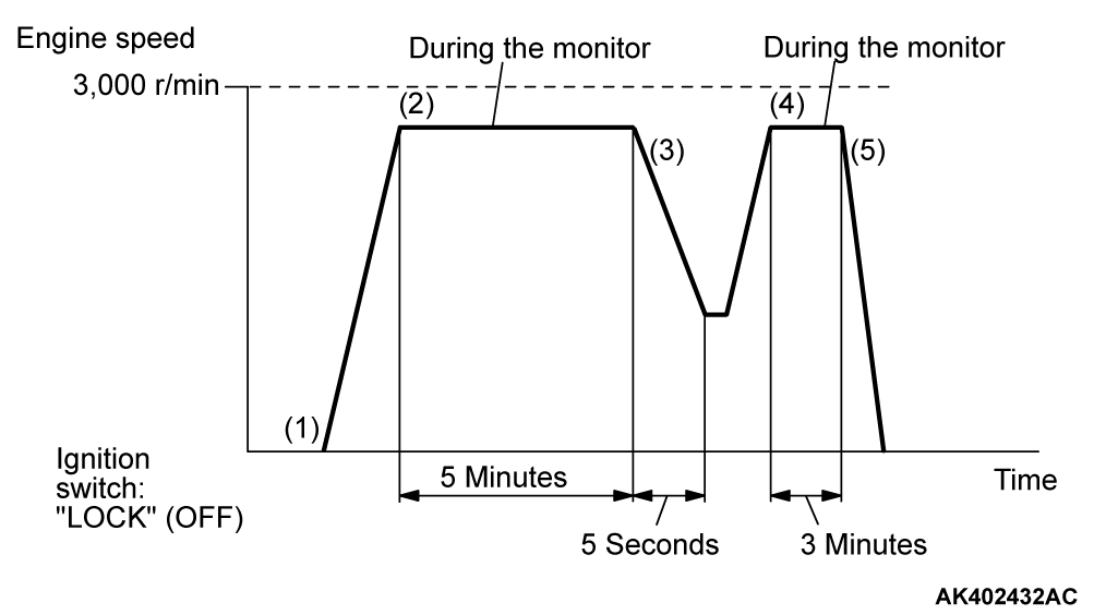
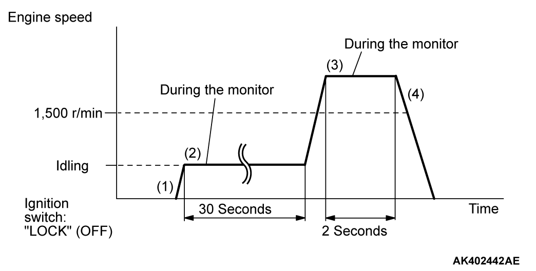
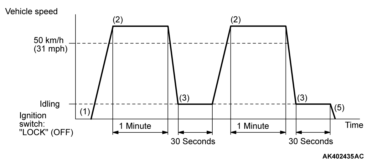
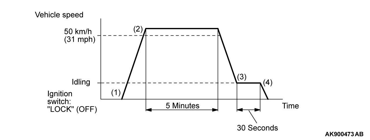
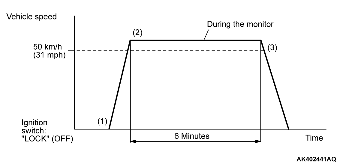
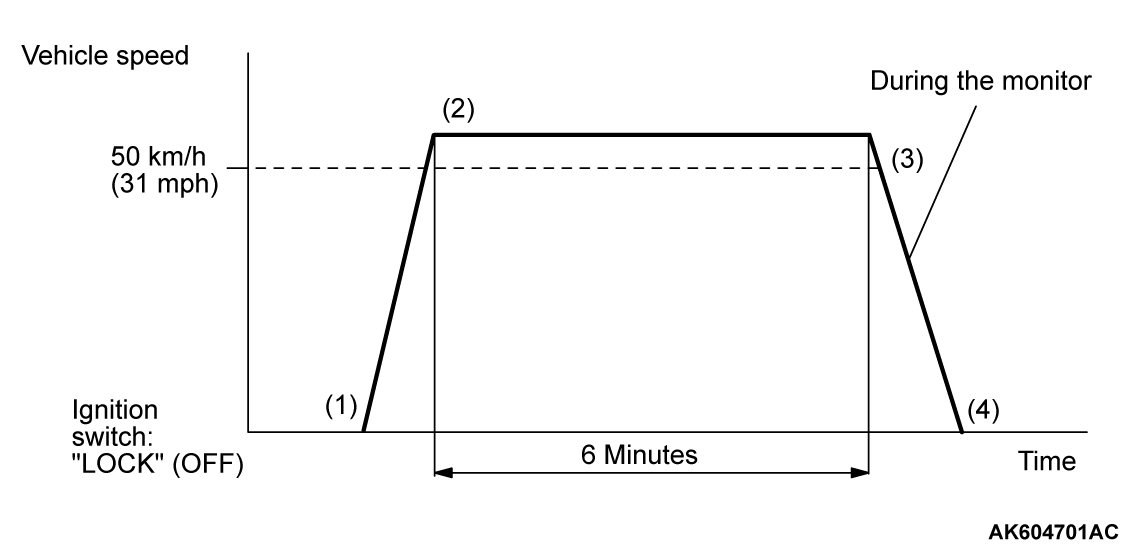
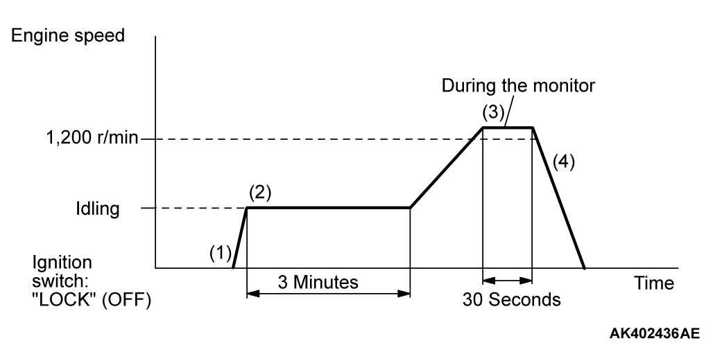
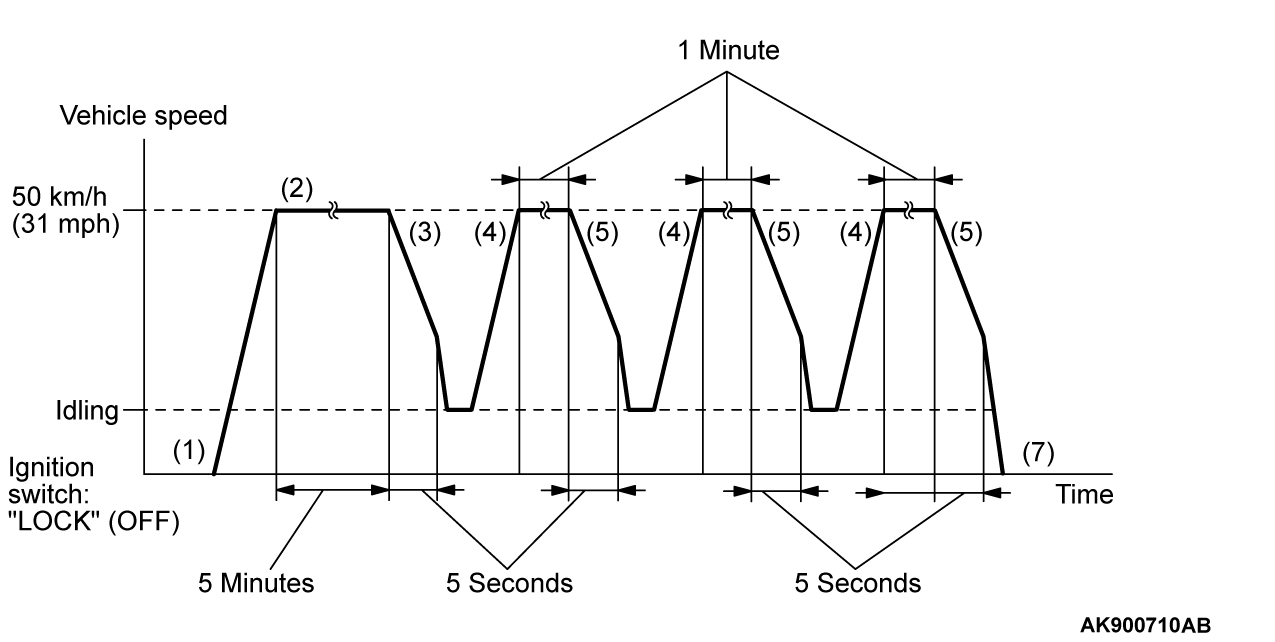
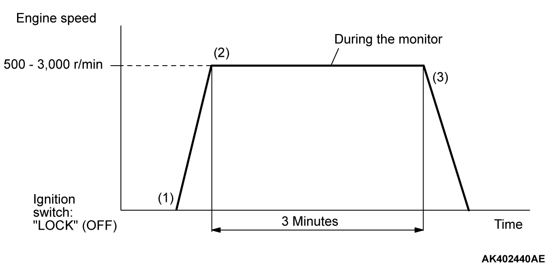
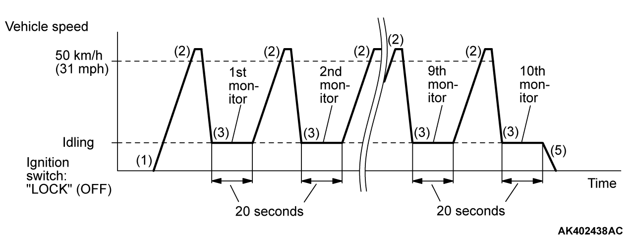
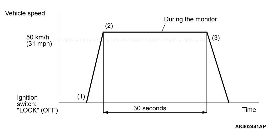
All kinds of diagnostic trouble codes (DTCs) can be monitored by carrying out a short drive according to the following 24 drive cycle patterns. In other words, doing such a drive regenerates any kind of trouble which involves illuminating the Malfunction Indicator Lamp (SERVICE ENGINE SOON or Check Engine Lamp) and verifies the repair procedure has been eliminated [the trouble the Malfunction Indicator Lamp (SERVICE ENGINE SOON or Check Engine Lamp) is no longer illuminated].| caution | Two technicians should always be in the vehicle when carrying out a test. |
| note | Check that the diagnostic trouble code (DTC) is not set before driving the OBD-II drive cycle. Erase the DTC if it has been set. |
| note | Drive cycle patterns are not established for Fuel level sensor monitor (DTC P0461, P2066 <AWD>). Please reference the M.U.T. data list to judge whether these monitor items are normal. |
DRIVE CYCLE PATTERN LIST
PATTERN 1
| Drive cycle pattern | |||||
| Inspection conditions |
| ||||
| Test procedure |
|
PATTERN 2
| Test procedure |
|
PATTERN 3
| Drive cycle pattern | |||
| Inspection conditions |
| ||
| Test procedure |
|
PATTERN 4
| Drive cycle pattern | |||||
| Inspection conditions |
| ||||
| Test procedure |
|
PATTERN 5
| Drive cycle pattern | |||||||
| Inspection conditions |
| ||||||
| Test procedure |
|
PATTERN 6
| Inspection conditions |
| ||||
| Test procedure |
|
PATTERN 7
| Drive cycle pattern | |
| Inspection conditions |
|
| Test procedure |
|
PATTERN 8
| Drive cycle pattern | |
| Inspection conditions |
|
| Test procedure |
|
PATTERN 9
| Drive cycle pattern | |
| Inspection conditions |
|
| Test procedure |
|
PATTERN 10
| Drive cycle pattern | |||
| Inspection conditions |
| ||
| Test procedure |
|
PATTERN 11
| Drive cycle pattern | |||
| Inspection conditions |
| ||
| Test procedure |
|
PATTERN 12
| Drive cycle pattern | |
| Inspection conditions |
|
| Test procedure |
|
PATTERN 13
| Drive cycle pattern | |||
| Inspection conditions |
| ||
| Test procedure |
|
PATTERN 14
| Inspection conditions |
|
| Test procedure |
|
PATTERN 15
| Drive cycle pattern | |
| Inspection conditions |
|
| Test procedure |
|
PATTERN 16
| Drive cycle pattern | |
| Inspection condition | Condition of CVT: Selector lever "D" range |
| Test procedure |
|
PATTERN 17
| Drive cycle pattern | |
| Inspection conditions |
|
| Test procedure |
|
PATTERN 18
| Inspection conditions |
|
| Test procedure |
|
PATTERN 19
| Inspection conditions |
|
| Test procedure |
|
PATTERN 20
| Inspection condition | Engine coolant temperature: More than 77°C (171°F), less than 87°C (189°F) |
| Test procedure |
|
PATTERN 21
| Inspection condition | Engine coolant temperature: More than 76°C (169°F) |
| Test procedure |
|
PATTERN 22
| Inspection conditions |
|
| Test procedure |
|
PATTERN 23
| Inspection conditions |
|
| Test procedure |
|
PATTERN 24
| Inspection conditions | Engine coolant temperature: More than 77°C (171°F) then engine cold state |
| Test procedure |
|
SYSTEM READINESS TEST STATUS
PURPOSE
The Readiness function (also referred to as I/M Readiness or I/M Flags) indicates if a full diagnostic check has been "Completed" (is "Ready") for each non-continuous monitor. Enhanced I/M State Emission Programs will use the Readiness status (Codes) to see if the vehicle is ready for OBD-II testing. "Incomplete" (Not Ready) codes will be one of the triggers for I/M failure.
OVERVIEW
The ECM monitors the following main diagnosis items and records whether the evaluation was completed or is incomplete. The Readiness Codes are established for the I/M programs, thereby confirming that the vehicles have not been tampered with by erasing the diagnostic trouble code(s) (DTCs) before I/M testing. The Readiness Codes and DTCs can be set again by disconnecting the battery or by erasing the codes with a scan tool MB991958 (M.U.T.-III sub assembly). For this reason, all the Readiness Codes must be displayed "Complete" before I/M testing.
When the monitors run and complete, the scan tool MB991958 (M.U.T.-III sub assembly) will display the Readiness Codes as "Complete" (General Scan Tools display as "Ready"). When the vehicle is operating normally and the OBD-II Drive Cycle is carried out, the Readiness Codes will be set as "Complete" on the first drive cycle. For DTCs requiring two drive cycles to detect a fault, the second drive cycle is required to set the Readiness Codes as "Complete" if a fault is detected during the first drive cycle. If the fault is still there after the second drive cycle, a DTC will be set.
- Catalyst: P0420
- Evaporative system: P0442, P0455, P0456
- Linear air-fuel ratio sensor: P0133, P014C, P014D, P015A, P015B
- Linear air-fuel ratio sensor heater: P0031, P0032, P0053
- Heated oxygen sensor: P0139, P0140
- Heated oxygen sensor heater: P0037, P0038
- EGR system: P0400
- V.V.T. system: P0011, P0014
After all the Readiness Codes are displayed as "Complete", the technician is assured that any DTCs related to the monitor will be displayed if the system has a problem. That is why some State's I/M programs require the Readiness Code as "Complete" before they check for DTCs.
| note | After a repair is made for a DTC, the technician should drive the OBD-II Drive Cycle checking that the scan tool MB991958 (M.U.T.-III Sub Assembly) displays all the Readiness Codes as "Complete". |
![[Previous]](../../../buttons/fprev.png)
![[Next]](../../../buttons/fnext.png)
