DTC P0AA4: Main contactor N weld
| danger |
| caution | Before replacing the ECU, ensure that the communication circuit is normal. |
DESCRIPTIONS OF MONITOR METHODS
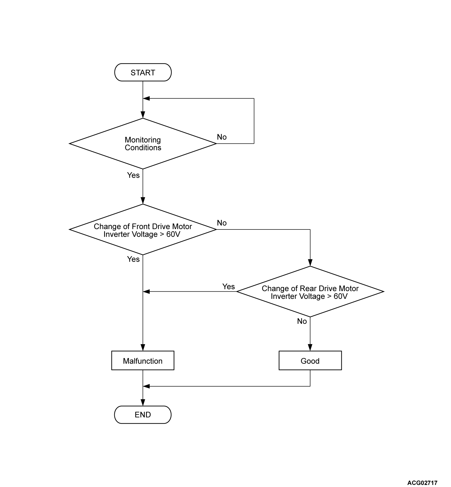
- The inverter voltage of the front electric motor control unit (FEMCU) or rear electric motor control unit (REMCU) is monitored to judge ON/OFF status of each contactor.
- The stuck on failure of each contactor is judged under the following conditions.
- Main contactor (N) stuck ON: Main contactor (P) control circuit active command off.
- Main contactor (N) stuck ON: Main contactor (N) control circuit active command off.
- Main contactor (N) stuck ON: Charging contactor control circuit active command on.
MONITOR EXECUTION
- Continuous
MONITOR EXECUTION CONDITIONS (Other monitor and Sensor)
Other Monitor (There is no temporary DTC stored in memory for the item monitored below)
- EV-CAN monitor
- Front electric motor control unit (FEMCU) current monitor
- Front electric motor control unit (FEMCU) coil temperature monitor
- Front electric motor control unit (FEMCU) IGBT temperature monitor
- Front electric motor control unit (FEMCU) capacitor temperature monitor
- Front electric motor control unit (FEMCU) control module temperature monitor
- Front electric motor control unit (FEMCU) 3 phase circuit monitor
- Rear electric motor control unit (REMCU) current monitor
- Rear electric motor control unit (REMCU) coil temperature monitor
- Rear electric motor control unit (REMCU) IGBT temperature monitor
- Rear electric motor control unit (REMCU) capacitor temperature monitor
- Rear electric motor control unit (REMCU) control module temperature monitor
- Rear electric motor control unit (REMCU) 3 phase circuit monitor
- Front electric motor control unit (FEMCU) inverter voltage monitor
- Rear electric motor control unit (REMCU) inverter voltage monitor
- Front electric motor control unit (FEMCU) Control module circuit monitor
- Rear electric motor control unit (REMCU) control module circuit monitor
Sensor (The sensor below is determined to be normal)
- Front electric motor control unit (FEMCU) current sensor
- Front electric motor control unit (FEMCU) coil temperature sensor
- Front electric motor control unit (FEMCU) position sensor
- Front electric motor control unit (FEMCU) IGBT temperature sensor
- Front electric motor control unit (FEMCU) capacitor temperature sensor
- Front electric motor control unit (FEMCU) control module temperature sensor
- Rear electric motor control unit (REMCU) current sensor
- Rear electric motor control unit (REMCU) coil temperature sensor
- Rear electric motor control unit (REMCU) position sensor
- Rear electric motor control unit (REMCU) IGBT temperature sensor
- Rear electric motor control unit (REMCU) capacitor temperature sensor
- Rear electric motor control unit (REMCU) control module temperature sensor
- Front electric motor control unit (FEMCU) inverter voltage sensor
- Rear electric motor control unit (REMCU) inverter voltage sensor
DTC SET CONDITIONS
Check Conditions
- The charging contactor activation command on.
- The main contactor (P) activation command off.
- The main contactor (N) activation command off.
- Time after above conditions satisfy is 0.4 second.
Judgment Criterion
- Change of the front electric motor control unit (FEMCU) voltage is more than 60 volts for immediately.
- Change of the rear electric motor control unit (REMCU) voltage is more than 60 volts for immediately.
PROBABLE CAUSES
- Damaged harness or connector.
- Malfunction of charge contactor.*
- Malfunction of main contactor (N) (weld).*
- Malfunction of electric heater.*
- Malfunction of the A/C compressor.*
- Malfunction of the on board charger/DC-DC converter.*
- Malfunction of the FEMCU.*
- Malfunction of the REMCU.*
- Malfunction of the GCU.*
- Malfunction of the AC converter. <Vehicles with AC power supply>*
- Malfunction of the PHEV-ECU.
| note | *: Welding is caused when the high voltage circuit of the high voltage components stays on. |
DIAGNOSIS
Required Special Tools
- MB991223: Wiring harness set
- MB992006: Extra fine probe
STEP 1. Check the signal line for short to power supply circuit (PHEV-ECU connector and main drive lithium-ion battery connector).
(1) Disconnect the connector and measure at the harness connector side.
(2) Check the wiring harness between PHEV-ECU connector and the main drive lithium-ion battery connector (terminal CNT-).
Is the check result normal?
STEP 2. Voltage measurement at high-voltage, service plug connector
| danger |
|
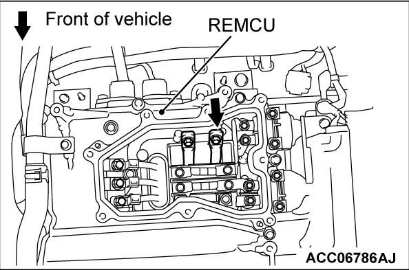
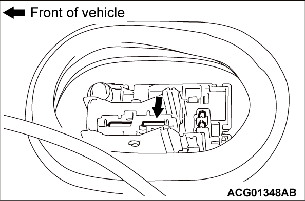
(2) Connect a high-voltage compatible multimeter between the main drive lithium-ion battery high-voltage terminal (REMCU) and the main drive lithium-ion battery service plug rear terminal.
OK: Approximately 0 volt
Is the check result normal?
STEP 3. Using scan tool (M.U.T.-IIISE), check whether the other DTC is set.
Check whether the other DTC, which is associated with the FEMCU, the GCU, the REMCU, the inverter (incorporated in the on-board charger/DC-DC converter), is set in the PHEV-ECU (Refer to  ).
).
 ).
).Is any DTC set?
STEP 4. Using scan tool (M.U.T.-IIISE), check whether the other DTC is set.
Check whether DTC is set in the A/C-ECU, A/C compressor assembly and electric heater-ECU (Refer to GROUP 55 - Diagnostic Trouble Code Chart  <A/C-ECU>,
  <A/C compressor assembly>,
  <electric heater-ECU>).
 <A/C-ECU>,
  <A/C compressor assembly>,
  <electric heater-ECU>).
Is the DTC set?
STEP 5. Check the electric heater ON failure.
| danger |
|
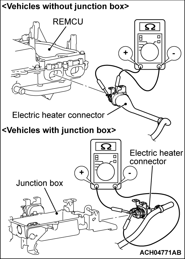
(2) Disconnect the electric heater connector (high voltage) and measure at the equipment side.
(3) Measure the resistance between electric heater connector (high voltage) (terminal No.1 and No.2).
OK: No continuity (Reference value: 1 MΩ or more)
| note | If you mistake the polarity of the tester, you can not measure correctly. |
Is the check result normal?
![[Previous]](../../../buttons/fprev.png)
![[Next]](../../../buttons/fnext.png)


