P0D6B-00 Electric Compressor Input Voltage Circuit Low
| danger |
|
| caution |
|
MONITOR EXECUTION
Continuous
MONITOR EXECUTION CONDITIONS (Other monitor and Sensor)
Other Monitor (There is no temporary DTC stored in memory for the item monitored below)
- Not applicable
Sensor (The sensor below is determined to be normal)
- Not applicable
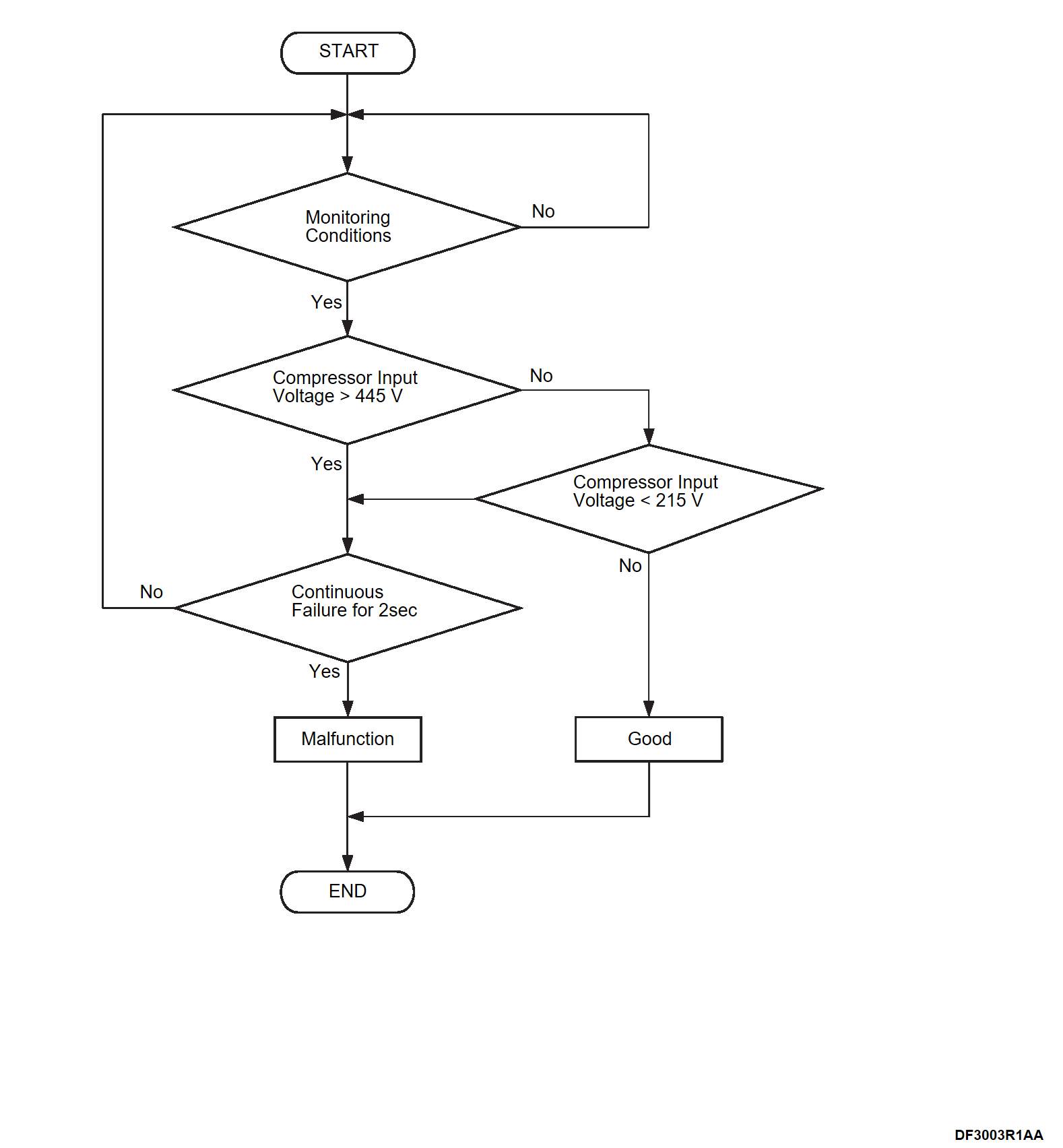
TROUBLE JUDGMENT
Check Condition
- The heater PHEV A/C amp. power supply voltage is between 10 and 16 volts.
- The drive battery voltage is between 240 volts and 408 volts.
Judgment Criterion
- Change the A/C compressor input voltage is less than 215 volts for 2 seconds.
OBD-II DRIVE CYCLE PATTERN
- Refer to OBD-II Drive Cycle – Pattern 4 OBD-II DRIVE CYCLE
 .
.
PROBABLE CAUSES
- Malfunction of CAN bus lines (HV1-CAN)
- Malfunction of LIN bus lines
- Malfunction of high voltage circuit
- Malfunction of power drive unit
- Malfunction of PHEV A/C amp.
- Malfunction of A/C compressor
DIAGNOSIS PROCEDURE
1.M.U.T.-III SE CAN bus diagnosis
Use M.U.T.-III SE to diagnose the CAN bus line. Repair the CAN bus line. (Trouble Diagnosis Flow Chart
 )
)
Is the inspection result normal?
 Repair the CAN bus line. (Trouble Diagnosis Flow Chart
 )
)2.M.U.T.-III SE other DTC
Check whether the PHEV A/C amp. sets the following DTCs related. Troubleshoot the set DTCs.
- DTC No. U1D21-87
- DTC No. U1D24-87
- DTC No. U2144-87
Are the DTCs set?
 Troubleshoot the set DTCs.
3.Check the installation between the A/C compressor high voltage cable connectors and power drive unit high voltage cable connectors.
| danger |
|
Is the inspection result normal?
 Repair or replace the connectors.
4.Check the continuity of the high voltage fuse (40 A) in the power drive unit inverter.
Refer to CHECK AND REPLACEMENT OF THE HIGH-VOLTAGE FUSE INSIDE THE INVERTER .
. Replace high voltage fuse. Refer to CHECK AND REPLACEMENT OF THE HIGH-VOLTAGE FUSE INSIDE THE INVERTER
 .
.
 .
.Is the inspection result normal?
 Replace high voltage fuse. Refer to CHECK AND REPLACEMENT OF THE HIGH-VOLTAGE FUSE INSIDE THE INVERTER
 .
.5.Check the continuity of the high voltage circuit in the power drive unit inverter.
| danger |
|
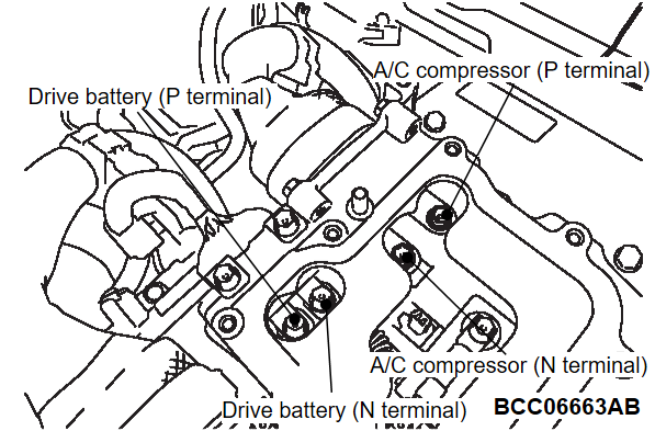
(1) Check the continuity between the drive battery (P terminal) and A/C compressor (P terminal).
OK : Continuity exists (2 Ω or less)
(2) Check the continuity between the drive battery (N terminal) and A/C compressor (N terminal).
OK : Continuity exists (2 Ω or less)
Is the inspection result normal?
 Replace power drive unit. Refer to POWER DRIVE UNIT REMOVAL AND INSTALLATION
 .
.6.Test the OBD-II drive cycle.
(1) Carry out a test drive with the drive cycle pattern. Refer to OBD-II Drive Cycle - Pattern 4 OBD-II DRIVE CYCLE .
.
 .
.(2) Check the DTC.
Is the DTC set?
 Replace PHEV A/C amp. Refer to Removal and Installation
 . then
 The trouble can be an intermittent malfunction. Refer to General Information - How to Use Troubleshooting/Inspection Service Points, How to Cope with Intermittent Malfunctions HOW TO COPE WITH INTERMITTENT MALFUNCTIONS
 .
.7.Test the OBD-II drive cycle.
(1) Carry out a test drive with the drive cycle pattern. Refer to OBD-II Drive Cycle - Pattern 4 OBD-II DRIVE CYCLE .
.
 .
.(2) Check the DTC.
Is the DTC set?
 Replace A/C compressor Refer to Removal and Installation
 .
. INSPECTION END
![[Previous]](../../../buttons/fprev.png)
![[Next]](../../../buttons/fnext.png)

