DTC P0053-00: Linear A/F Sensor Heater deterioration
CIRCUIT OPERATION
- MFI relay is built into the IPDM E/R.
- Power is supplied to the heater power terminal of the linear air-fuel ratio sensor connector terminal number 3 from the MFI relay connector terminal.
- The heater of the linear air-fuel ratio sensor is controlled by the power transistor in the ECM connector terminal number 1.
TECHNICAL DESCRIPTION
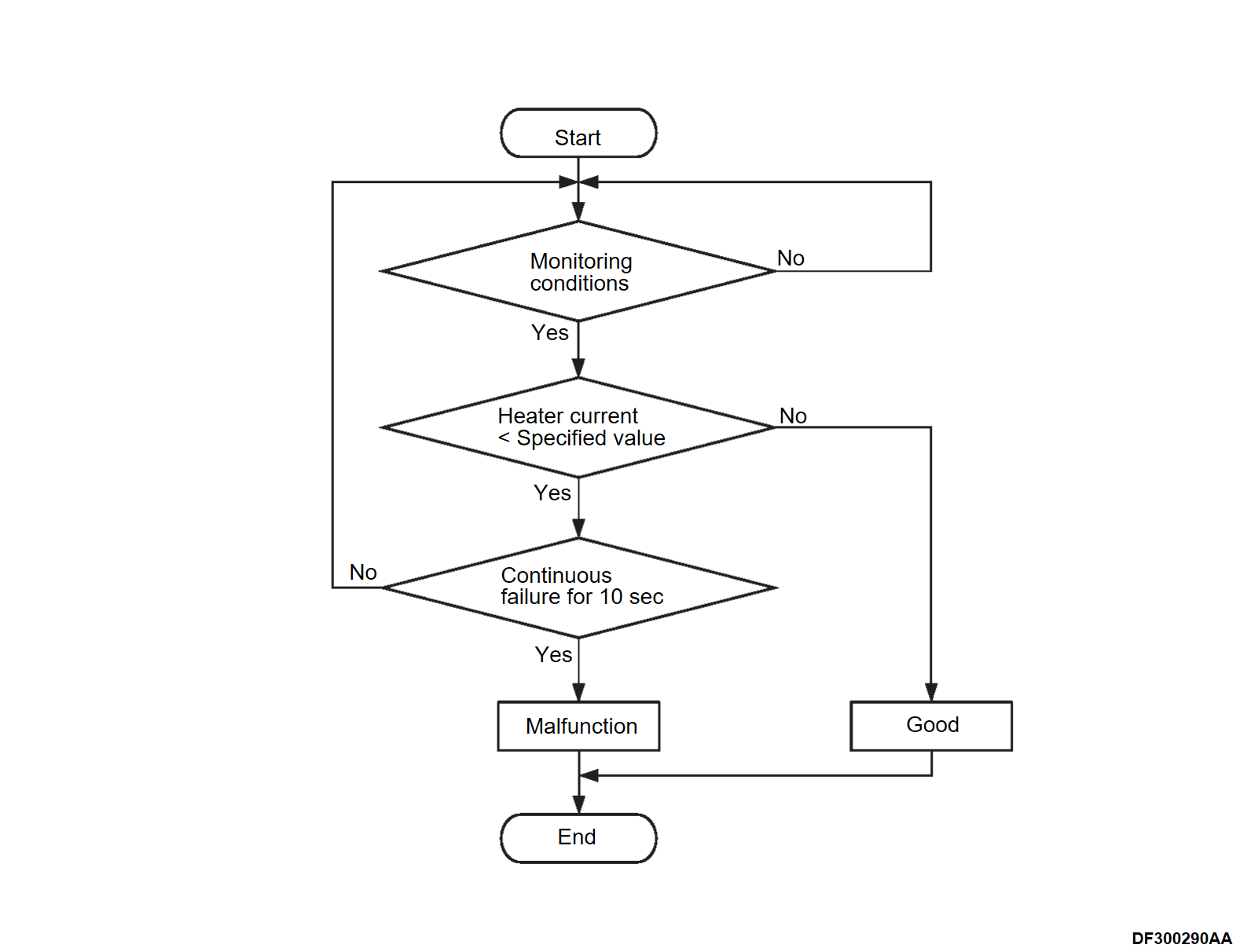
The ECM checks whether the heater current is within a specified range when the heater is energized.
DESCRIPTIONS OF MONITOR METHODS
Linear air-fuel ratio sensor heater current is out of specified range.
MONITOR EXECUTION
Continuous.
MONITOR EXECUTION CONDITIONS (Other monitor and Sensor)
Other Monitor (There is no temporary DTC set in memory for the item monitored below)
- Not applicable
Sensor (The sensor below is determined to be normal)
- Not applicable
Check Conditions
- While the linear air-fuel ratio sensor heater is on.
- 12V battery positive voltage is between 11.0 and 16.5 volts.
- More than 220 seconds have passed since the engine starting sequence was completed.
- Intake air temperature is higher than –10°C (14°F).
- On duty cycle of the linear air-fuel ratio sensor heater is between 25 and 75 percent.
Judgment Criterion
- The linear air-fuel ratio sensor heater current has continued to be lower than average 0.58 ampere for 10 seconds.
FAIL-SAFE AND BACKUP FUNCTION
None.
OBD-II DRIVE CYCLE PATTERN
Refer to Diagnostic Function, OBD-II Drive Cycle – Pattern 2 OBD- II DRIVE CYCLE .
.
 .
.TROUBLESHOOTING HINTS (The most likely causes for this code to be set are:)
- Linear air-fuel ratio sensor circuit harness damage or connector damage.
- Linear air-fuel ratio sensor heater failed.
- ECM failed.
DIAGNOSIS
Required Special Tools:
- MB992744: Vehicle communication interface-Lite (V.C.I.-Lite)
- MB992745: V.C.I.-Lite main harness A
- MB992747: V.C.I.-Lite USB cable short
- MB992748: V.C.I.-Lite USB cable long
1.STEP 1. Check linear air-fuel ratio sensor itself.
Check linear air-fuel ratio sensor itself (Refer to LINEAR AIR-FUEL RATIO SENSOR CHECK ).
). Replace the linear air-fuel ratio sensor (Refer to ENGINE, Engine, Motor and Emission Control – Emission Control – Exhaust Gas Purification System CATALYTIC CONVERTER REMOVAL AND INSTALLATION
 ).
).
 ).
).Q: Is the check result normal?
 Replace the linear air-fuel ratio sensor (Refer to ENGINE, Engine, Motor and Emission Control – Emission Control – Exhaust Gas Purification System CATALYTIC CONVERTER REMOVAL AND INSTALLATION
 ).
).2.STEP 2. Check harness between linear air-fuel ratio sensor connector terminal number 3 and IPDM E/R connector terminal number 75.
Check power supply line for damage. Repair or replace the connector, or repair the damaged harness wire.
Q: Is the check result normal?
 Repair or replace the connector, or repair the damaged harness wire.
3.STEP 3. Check harness between linear air-fuel ratio sensor connector terminal number 4 and ECM connector terminal number 1.
Check ground line for damage. Repair or replace the connector, or repair the damaged harness wire.
Q: Is the check result normal?
 Repair or replace the connector, or repair the damaged harness wire.
4.STEP 4. Test the OBD-II drive cycle.
After erasing the DTC, carry out test drive with the drive cycle pattern, and recheck the DTC. Replace the ECM (Refer to ENGINE CONTROL MODULE (ECM) REMOVAL AND INSTALLATION
 ).
). Intermittent malfunction (Refer to GENERAL INFORMATION, General Information – How to Use Troubleshooting/Inspection Service Points – How to Cope with Intermittent Malfunctions HOW TO COPE WITH INTERMITTENT MALFUNCTIONS
 ).
).
(1) Use scan tool (M.U.T.-III SE) to erase the DTC.
(2) Carry out test drive with the drive cycle pattern (Refer to Diagnostic Function, OBD-II Drive Cycle – Pattern 2 OBD- II DRIVE CYCLE ).
).
 ).
).(3) Use scan tool (M.U.T.-III SE) to recheck the DTC.
Is DTC P0053-00 set?
 Replace the ECM (Refer to ENGINE CONTROL MODULE (ECM) REMOVAL AND INSTALLATION
 ).
). Intermittent malfunction (Refer to GENERAL INFORMATION, General Information – How to Use Troubleshooting/Inspection Service Points – How to Cope with Intermittent Malfunctions HOW TO COPE WITH INTERMITTENT MALFUNCTIONS
 ).
).![[Previous]](../../../buttons/fprev.png)
![[Next]](../../../buttons/fnext.png)
