[Previous][Next]
OBD- II DRIVE CYCLE
 
 
All kinds of Diagnostic Trouble Codes (DTCs) can be monitored by carrying out a short drive according to the following five drive cycle patterns. In other words, doing such a drive regenerates any kind of trouble which involves illuminating the malfunction indicator lamp (SERVICE ENGINE SOON or check engine lamp) and verifies that the trouble has been eliminated [the malfunction indicator lamp (SERVICE ENGINE SOON or check engine lamp) is no longer illuminated].
cautionTwo technicians should always be in the vehicle when carrying out a test.
noteCheck that the DTC is not set before driving the OBD-II drive cycle. Erase the DTC with scan tool (M.U.T.-III SE) if it has been set.
DRIVE CYCLE PATTERN LIST
MONITOR ITEMDIAGNOSTIC TROUBLE CODE (DTC)PATTERN
Barometric pressure sensor/Manifold absolute pressure correlationP0069-00
Bypass valve monitorP1445-14, P1446-12
Camshaft position sensor monitorP0340-00
Canister pressure sensor monitorP24BA-00, P24BB-00
Controller area network (CAN) monitorU0111-00, U0146-00, U0155-00, U025E-00, U0293-00, U0594-00, U1E05-87
Crankshaft position sensor monitorP061C-00
Engine coolant temperature sensor monitorP0117-00, P0118-00
Evaporative emission purge solenoid monitorP0458-00, P0459-00
Exhaust gas recirculation (EGR) system monitorP0489-00, P0490-00
Exhaust gas recirculation (EGR) temperature sensor monitorP040B-00, P040C-00, P040D-00, P04FA-00
Fuel level sensor monitorP0462-00, P0463-00
Fuel tank differential pressure sensor monitorP0452-00, P0453-00
Fuel tank pressure sensor monitorP24D7-00, P24D8-00
Fuel tank solenoid valve monitorP2419-00, P2420-00
Heated oxygen sensor (rear) heater monitor <Readiness test item>P0037-00, P0038-00
Heated oxygen sensor (rear) offset voltage monitorP2252-00, P2253-00
Fuel injector monitorP0261-00, P0262-00, P0264-00, P0265-00, P0267-00, P0268-00, P0270-00, P0271-00
Intake air temperature sensor monitorP0112-00, P0113-00
Keep alive memory monitorP1603-14
Knock sensor monitorP0327-00, P0328-00
Linear air-fuel ratio sensor heater monitor <Readiness test item>P0031-00, P0032-00
Linear air-fuel ratio sensor monitorP0130-00, P0131-00, P0132-00, P2237-00, P2243-00, P2251-00
Manifold absolute pressure (MAP) sensor monitorP0106-00, P0107-00, P0108-00
Mass airflow sensor monitorP0068-00, P0100-00, P0102-00, P0103-00, U060F-00
Mass airflow sensor/Throttle position sensor monitorP1238-64
OverheatP1217-98
Switching valve monitorP24BE-00, P24BF-00
Throttle actuator control motor monitorP2100-00, P2101-00
Throttle actuator control motor relay monitorP0657-00
Throttle position sensor (main and/or sub) monitorP2135-00
Throttle position sensor (main) monitorP0121-00, P0122-00, P0123-00
Throttle position sensor (sub) monitorP0221-00, P0222-00, P0223-00
Throttle valve control monitorP0638-00
Air-fuel ratio feedback control system monitorP2096-00, P2097-00
Engine coolant temperature sensor monitorP0116-00, P0125-00
Evaporative emission purge solenoid monitorP04DF-00
Evaporative emission purge system monitor <Readiness test item>P0441-00
Fuel system monitorP0171-00, P0172-00
Heated oxygen sensor (rear) monitorP0137-00, P0138-00
Ignition timing retard control (cold start strategy) monitorP050B-00
Linear air-fuel ratio sensor heater monitor <Readiness test item>P0053-00
Linear air-fuel ratio sensor monitorP0134-00
Misfire monitorP0300-00, P0301-00, P0302-00, P0303-00, P0304-00
Variable valve timing system (MIVEC) monitorP0016-00
Non-volatile random access memory (NVRAM) monitorP0630-00
Thermostat monitorP0128-00
Bypass valve monitorP1450-72, P1451-73
Canister pressure sensor monitorP1469-62, P24B9-00
Engine coolant temperature/Intake air temperature correlationP011B-00
Evaporative emission purge solenoid monitorP04E0-00
Evaporative emission purge system leakage monitor <Readiness test item>P04EC-00, P04ED-00, P04EE-00, P04EF-00
Evaporative leak check pump/Reference orifice monitorP043E-00, P043F-00
Evaporative leak check pump/Switching valve monitorP24C0-00
Evaporative leak check pump monitorP1401-09
Exhaust gas recirculation (EGR) temperature sensor monitorP040F-00
Fuel tank differential pressure sensor monitorP0451-00, P0454-00
Fuel tank pressure sensor monitorP24D6-00, P24D9-00
Fuel tank solenoid valve monitorP2450-00, P2451-00
Fuel tank vapor line monitorP00FE-00
Switching valve monitorP24C1-00
Air-fuel cylinder imbalance monitorP219A-00
Catalytic converter monitor <Readiness test item>P0421-00
Crankshaft position sensor monitorP0335-00
Exhaust gas recirculation (EGR) system monitor <Readiness test item>P0400-00, P0402-00
Fuel tank differential pressure sensor monitorP0450-00
Heated oxygen sensor (rear) monitor <Readiness test item>P0139-00, P0140-00
Intake air temperature sensor monitorP0111-00
Linear air-fuel ratio sensor monitor <Readiness test item>P0133-00, P014C-00, P014D-00, P015A-00, P015B-00
Variable valve timing system (MIVEC) monitorP0010-00
Variable valve timing system (MIVEC) monitor <Readiness test item>P0011-00
Fuel level sensor monitorP0461-00
 
 
PATTERN 1
Inspection conditionCharging status: 30 to 70 percent
noteFor the charging status, use scan tool (M.U.T.-III SE) check the BMU data list item number 35: SOC CAN Output [Refer to ELECTRIC POWER TRAIN, Battery Management Unit (BMU) and Traction Battery – Troubleshooting DATA LIST REFERENCE TABLE].
Test procedure
noteIf the Charging state exceeds 70 percent during the test, carry out the discharge operation.
  1. Depress the brake pedal, and turn on (READY) the power supply mode of the electric motor switch.
  2. Set the vehicle to CHARGE mode to start the engine.
  3. Let the engine run for 10 seconds or more.
  4. Turn off the power supply mode of the electric motor switch, and wait until MFI relay turns off. (approximately 30 seconds)
  5. Repeat Steps 1 to 4 for 2 times.
  6. Confirm that the DTC is not set.
 
 
PATTERN 2
Inspection conditionCharging status: 30 to 70 percent
noteFor the charging status, use scan tool (M.U.T.-III SE) check the BMU data list item number 35: SOC CAN Output [Refer to ELECTRIC POWER TRAIN, Battery Management Unit (BMU) and Traction Battery – Troubleshooting DATA LIST REFERENCE TABLE].
Test procedure
noteIf the Charging state exceeds 70 percent during the test, carry out the discharge operation.
  1. Depress the brake pedal, and turn on (READY) the power supply mode of the electric motor switch.
  2. Set the vehicle to CHARGE mode to start the engine.
  3. Let the engine run for 180 seconds or more.
  4. Turn off the power supply mode of the electric motor switch, and wait until MFI relay turns off. (approximately 30 seconds)
  5. Repeat Steps 1 to 4 for 2 times.
  6. Confirm that the DTC is not set.
 
 
PATTERN 3
Drive cycle pattern
Inspection conditionCharging status: 30 to 70 percent
noteFor the charging status, use scan tool (M.U.T.-III SE) check the BMU data list item number 35: SOC CAN Output [Refer to ELECTRIC POWER TRAIN, Battery Management Unit (BMU) and Traction Battery – Troubleshooting DATA LIST REFERENCE TABLE].
Test procedure
noteIf the Charging state exceeds 70 percent during the test, carry out the discharge operation.
  1. Turn on the power supply mode of the electric motor switch and send the DTC erase signal from scan tool (M.U.T.-III SE) to the ECM.
  2. Depress the brake pedal, and turn on (READY) the power supply mode of the electric motor switch.
  3. Set the vehicle to CHARGE mode to start the engine.
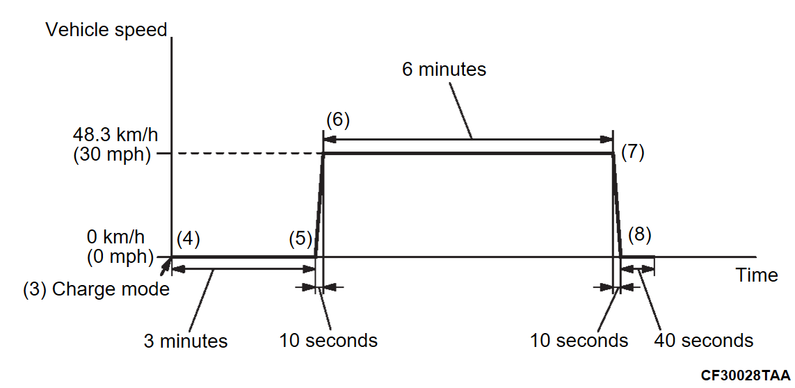
  4. Continue the vehicle stopped state for more than three minutes as it is.
  5. Accelerate until the vehicle speed reaches 48.3 km/h (30 mph) spending 10 seconds.
  6. Drive at a constant speed at 48.3 km/h (30 mph) for more than six minutes.
  7. Stop the vehicle spending 10 seconds.
  8. With the brake pedal depressed down, keep the vehicle stopped for 40 seconds or more.
  9. Turn off the power supply mode of the electric motor switch, and wait until MFI relay turns off. (approximately 30 seconds)
  10. Repeat Steps 2 to 9.
  11. Confirm that the DTC is not set.
 
 
PATTERN 4
Drive cycle pattern
Inspection condition
  • Charging status: 30 to 70 percent
    noteFor the charging status, use scan tool (M.U.T.-III SE) check the BMU data list item number 35: SOC CAN Output [Refer to ELECTRIC POWER TRAIN, Battery Management Unit (BMU) and Traction Battery – Troubleshooting DATA LIST REFERENCE TABLE].
  • Fuel amount: Less than 85 percent <DTC P00FE-00, P043E-00, P043F-00, P0451-00, P0454-00P04E0-00, P04EC-00, P04ED-00, P04EE-00, P04EF-00, P1401-09, P1450-72, P1451-73, P1469-62, P2450-00, P2451-00, P24B9-00, P24C0-00, P24C1-00, P24D6-00, P24D9-00>
Test procedure
noteIf the Charging state exceeds 70 percent during the test, carry out the discharge operation.
  1. Turn on the power supply mode of the electric motor switch and send the DTC erase signal from scan tool (M.U.T.-III SE) to the ECM.
  2. Depress the fuel filler lid opener switch and open the fuel cap.
  3. Close the fuel cap and close the fuel filler lid.
  4. Depress the brake pedal, and turn on (READY) the power supply mode of the electric motor switch.
  5. Set the vehicle to CHARGE mode to start the engine.
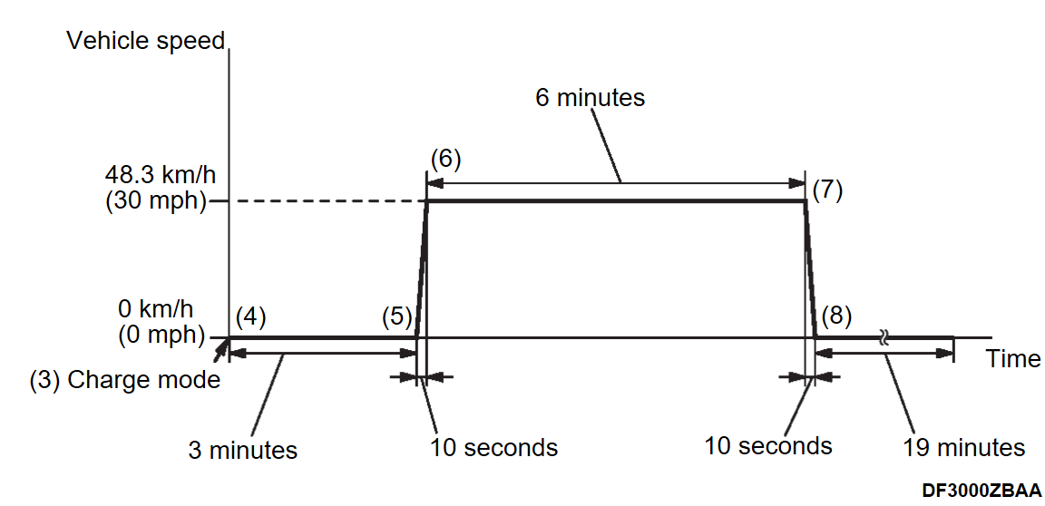
  6. Continue the vehicle stopped state for more than three minutes as it is.
  7. Accelerate until the vehicle speed reaches 48.3 km/h (30 mph) spending 10 seconds.
  8. Drive at a constant speed at 48.3 km/h (30 mph) for more than six minutes.
  9. Stop the vehicle spending 10 seconds.
  10. With the brake pedal depressed down, keep the vehicle stopped for 19 minutes or more.
  11. Turn off the power supply mode of the electric motor switch, and wait until MFI relay turns off. (approximately 30 seconds)
  12. Soak the vehicle for 7 hours.
  13. Repeat Step 4 to 12.
  14. Confirm that the DTC is not set.
 
 
PATTERN 5
Drive cycle pattern
Inspection condition
  • Charging status: 30 to 70 percent
    noteFor the charging status, use scan tool (M.U.T.-III SE) check the BMU data list item number 35: SOC CAN Output [Refer to ELECTRIC POWER TRAIN, Battery Management Unit (BMU) and Traction Battery – Troubleshooting DATA LIST REFERENCE TABLE].
  • Fuel amount: Less than 70 percent <DTC P0450-00>
Test procedure
noteIf the Charging state exceeds 70 percent during the test, carry out the discharge operation.
  1. Turn on the power supply mode of the electric motor switch and send the DTC erase signal from scan tool (M.U.T.-III SE) to the ECM.
  2. Depress the brake pedal, and turn on (READY) the power supply mode of the electric motor switch.
  3. Set the vehicle to CHARGE mode to start the engine.
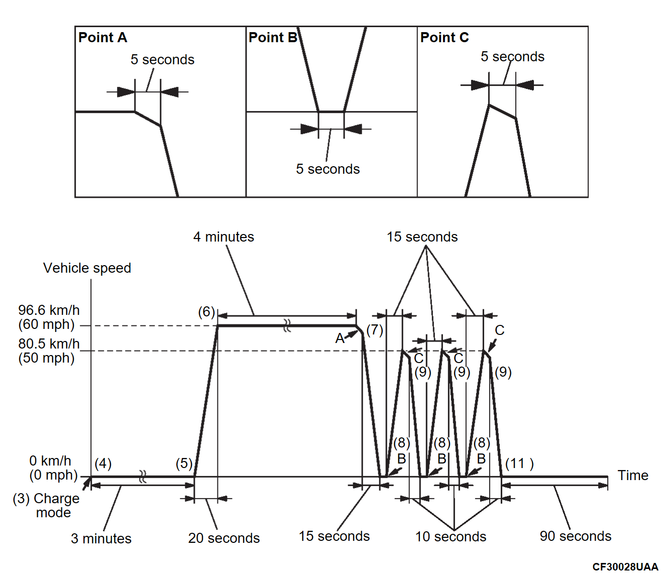
  4. Continue the vehicle stopped state for more than three minutes as it is.
  5. Accelerate until the vehicle speed reaches 96.6 km/h (60 mph) spending 20 seconds.
  6. Drive at a constant speed at 96.6 km/h (60 mph) for more than four minutes.
  7. Fully release your foot from the accelerator pedal and slow down for five seconds. Then stop the vehicle spending 15 seconds.
  8. After continuing the stopped state for more than five seconds, accelerate until the vehicle speed reaches 80.5 km/h (50 mph) spending 15 seconds.
  9. Fully release your foot from the accelerator pedal and slow down for five seconds. Then stop the vehicle spending 10 seconds.
  10. Repeat Step 8 to 9 for 2 times.
  11. With the brake pedal depressed down, keep the vehicle stopped for 90 seconds or more.
  12. Turn off the power supply mode of the electric motor switch, and wait until MFI relay turns off. (approximately 30 seconds)
  13. Repeat Steps 2 to 12.
  14. Confirm that the DTC is not set.
 
 
PATTERN 6
Drive cycle pattern
Inspection conditions
  • Fuel amount: Less than 85 percent
  • Charging status: 30 to 70 percent
    noteFor the charging status, use scan tool (M.U.T.-III SE) check the BMU data list item number 35: SOC CAN Output [Refer to ELECTRIC POWER TRAIN, Battery Management Unit (BMU) and Traction Battery – Troubleshooting DATA LIST REFERENCE TABLE].
Test procedure
  1. Turn on the power supply mode of the electric motor switch and send the DTC erase signal from scan tool (M.U.T.-III SE) to the ECM.
  2. Depress the brake pedal, and turn on (READY) the power supply mode of the electric motor switch.
  3. Set the vehicle to CONTINUOUS IDLING mode to start the engine.
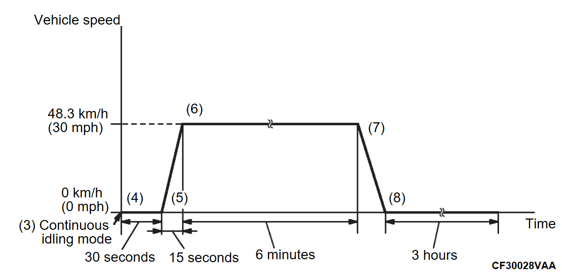
  4. Let the engine idle for 30 seconds.
  5. Accelerate until the vehicle speed reaches 48.3 km/h (30 mph) spending 15 seconds.
  6. Drive at a constant speed at 48.3 km/h (30 mph) for more than six minutes.
  7. Stop the vehicle in a safe place.
  8. Let the engine idle for three hours.
  9. Turn off the power supply mode of the electric motor switch, and wait until MFI relay turns off. (approximately 30 seconds)
  10. Repeat Steps 2 to 9.
  11. Confirm that the DTC is not set.
 
 
SYSTEM READINESS TEST STATUS
 
 
PURPOSE
The readiness function (also referred to as I/M readiness or I/M flags) indicates if a full diagnostic check has been "Completed" (is "Ready") for each non-continuous monitor. Enhanced I/M state emission programs will use the readiness status (Codes) to see if the vehicle is ready for OBD-II testing. "Incomplete" (Not ready) codes will be one of the triggers for I/M failure.
 
 
OVERVIEW
The ECM monitors the following main diagnosis items and records whether the evaluation was completed or is incomplete. The readiness codes are established for the I/M programs, thereby confirming that the vehicles have not been tampered with by erasing the DTCs before I/M testing. The readiness codes and DTCs can be set again by erasing the codes with a scan tool (M.U.T.-III SE). For this reason, all the readiness codes must be displayed "Complete" before I/M testing.
When the monitors run and complete, the scan tool (M.U.T.-III SE) will display the readiness codes as "Complete" (General Scan Tools display as "Ready"). When the vehicle is operating normally and the OBD-II drive cycle is carried out, the readiness codes will be generated as "Complete" on the first drive cycle. For DTCs requiring two drive cycles to detect a fault, the second drive cycle is required to generate the readiness codes as "Complete" if a fault is detected during the first drive cycle. If the fault is still there after the second drive cycle, a DTC will be set.
  • Catalyst: P0421-00
  • EGR and/or VVT system: P0011-00, P0400-00, P0402-00
  • Evaporative emission system: P0441-00, P04EC-00, P04ED-00, P04EE-00, P04EF-00
  • Fuel system: P219A-00
  • Heated oxygen sensor (rear): P0139-00, P0140-00
  • Heated oxygen sensor (rear) heater: P0037-00, P0038-00
  • Linear air-fuel ratio sensor: P0133-00, P014C-00, P014D-00, P015A-00, P015B-00
  • Linear air-fuel ratio sensor heater: P0031-00, P0032-00, P0053-00
After all the readiness codes are displayed as "Complete", the technician is assured that any DTCs related to the monitor will be displayed if the system has a problem. That is why some state's I/M programs require the readiness code as "Complete" before they check for DTCs.
noteAfter a repair is made for a DTC, the technician should drive the OBD-II drive cycle checking that the scan tool (M.U.T.-III SE) displays all the readiness codes as "Complete".