System Description
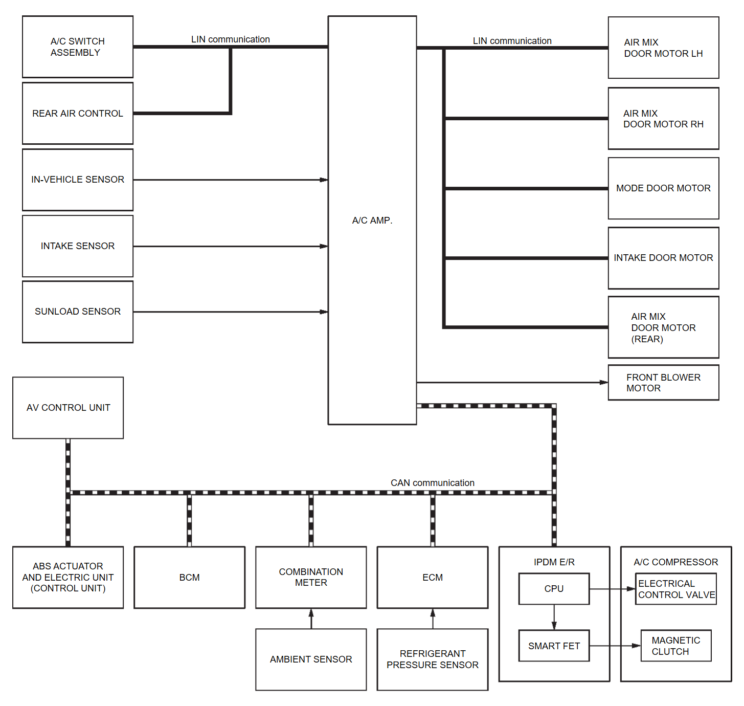
SYSTEM DIAGRAM
| Component | Function |
| ABS actuator and electric unit (control unit) | ABS actuator and electric unit (control unit) transmits vehicle speed signal to A/C amp. via CAN communication line. |
| AV control unit | AV control unit transmits blower reduction request signal to A/C amp. via CAN communication line. |
| A/C amp. | A/C Amp. |
| BCM | BCM transmits remote engine start status signal to A/C amp. via CAN communication line. |
| Combination meter | Combination meter transmits ambient temperature signal to A/C amp. via CAN communication line. |
| ECM |
|
| IPDM E/R |
|
| A/C switch assembly | A/C Switch Assembly |
| Rear air control* | Rear Air Control |
| Ambient sensor | Ambient Sensor |
| Intake sensor | Intake Sensor |
| In-vehicle sensor | In-vehicle Sensor |
| Refrigerant pressure sensor | Refrigerant Pressure Sensor |
| Sunload sensor | Sunload Sensor |
| Air mix door motor LH | Air Mix Door Motor LH |
| Air mix door motor RH | Air Mix Door Motor RH |
| Air mix door motor (Rear)* | Air Mix Door Motor (Rear) |
| Front blower motor | Front Blower Motor |
| Intake door motor | Intake Door Motor |
| Mode door motor | Mode Door Motor |
| A/C compressor | A/C Compressor |
*: With rear air control
INPUT/OUTPUT SIGNAL
| Control unit | Signal status |
| ABS actuator and electric unit (control unit) | Transmits the vehicle speed signal to A/C amp. via CAN communication. |
| AV control unit | Transmits the blower reduction request signal to A/C amp. via CAN communication. |
| BCM | Transmits the remote engine start status signal to A/C amp. via CAN communication. |
| Combination meter | Transmits the ambient temperature signal to A/C amp. via CAN communication. |
| ECM |
|
| IPDM E/R | Receives mainly the ECV control signal from A/C amp. via CAN communication. |
| A/C switch assembly |
|
| Rear air control* |
|
| Air mix door motor LH |
|
| Air mix door motor RH | |
| Air mix door motor (Rear)* | |
| Intake door motor | |
| Mode door motor |
*: With rear air control
DESCRIPTION
- Automatic air conditioning system is controlled by each function of A/C amp., ECM and IPDM E/R.
- Each operation of air conditioning system can be controlled by the A/C switch assembly.
CONTROL BY A/C amp.
CORRECTION FOR INPUT VALUE
- Ambient temperature correction
- A/C amp. inputs the temperature detected by ambient temperature signal received from combination meter via CAN communication as the ambient temperature.
- A/C amp. performs the correction of the temperature detected by ambient sensor for air conditioning control.
- A/C amp. selects and uses the initial value of ambient temperature data depending on the engine coolant temperature when turning the ignition switch from OFF to ON. The detection temperature of the ambient sensor is used when engine coolant temperature is low [less than approximately 56°C (133°F)]. The memory data (before the ignition switch is OFF) when the engine is warmed up [approximately 56°C (133°F) or more].
- The correction of the ambient temperature is not performed when the detection temperature of the ambient temperature is less than approximately −20°C (–4°F).
- In-vehicle temperature correction
- A/C amp. inputs the temperature detected by in-vehicle sensor as the in-vehicle temperature.
- A/C amp. performs the correction of the temperature detected by in-vehicle sensor for air conditioning control.
- A/C amp. performs the correction so that the recognition passenger room temperature changes depending on the difference between the detected passenger room temperature and the recognition passenger room temperature. If the difference is large, the changing is early. The changing becomes slow as the difference becomes small.
- Intake temperature correction
- A/C amp. inputs the temperature detected by intake sensor as the intake temperature (evaporator temperature).
- A/C amp. performs the correction of the temperature detected by intake sensor for air conditioning control.
- A/C amp. performs the correction so that the recognition intake temperature changes depending on the difference between the detected intake temperature and the recognition intake temperature. If the difference is large, the changing is early. The changing becomes slow as the difference becomes small.
- Sunload amount correction
- A/C amp. inputs the sunload amount detected by sunload sensor.
- A/C amp. performs the correction of the sunload amount detected by sunload sensor for air conditioning control.
- When the sunload amount suddenly changes, for example when entering a tunnel, perform the correction so that the recognition sunload amount of the A/C amp. changes slowly.
- Set temperature correction
- A/C amp. performs the correction to the target temperature set by the A/C switch assembly so as to match the temperature felt by the passengers depending on the ambient temperature detected by ambient sensor and controls it so that the in-vehicle temperature is always the most suitable.
CONTROL BY ECM
CONTROL BY IPDM E/R
![[Previous]](../../../buttons/fprev.png)
![[Next]](../../../buttons/fnext.png)
