Disassembly and Assembly
DISASSEMBLY
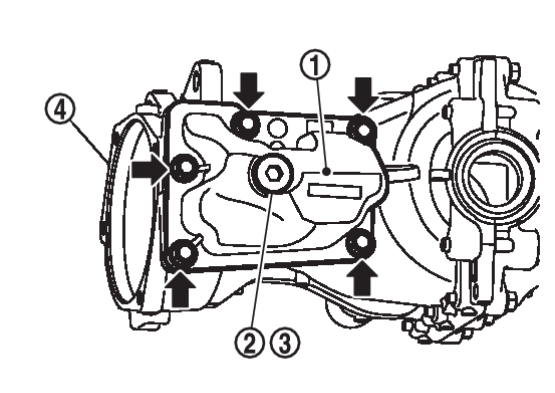
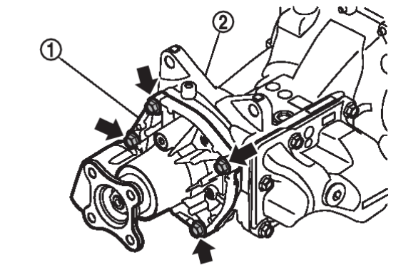
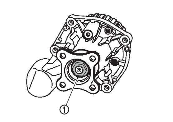
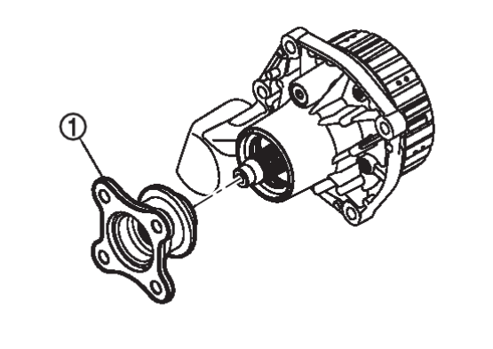
1. Remove electro-hydraulic coupling assembly  from final drive assembly
  after removing electro-hydraulic coupling assembly mounting bolts.
 from final drive assembly
  after removing electro-hydraulic coupling assembly mounting bolts.
| caution | Oil is drained from between electro-hydraulic coupling assembly and final drive assembly when removing, set a pan under them. |
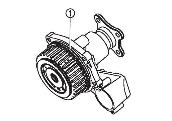
4. Remove O-ring  from electro-hydraulic coupling assembly.
 from electro-hydraulic coupling assembly.
| caution |
|
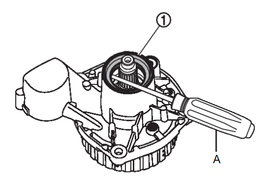
7. Remove electro-hydraulic coupling oil seal  using oil seal remover (A) (commercial service tool).
 using oil seal remover (A) (commercial service tool).
| caution | Never damage electro-hydraulic coupling assembly. |
9. Perform inspection after disassembly. Refer to Inspection .
.
 .
.ASSEMBLY
| caution | Be careful to place each part so that the contamination never stick to the drum surface and the mating surface of the companion flange during work. |
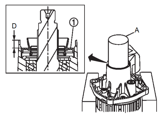
1. Using the drift (A) (commercial service tool), install electro-hydraulic coupling oil seal  as shown in the figure.
 as shown in the figure.
| Installation dimension | |
| D | : 7.15 ±0.1 mm (0.2815 ±0.004 in) |
| caution |
|
3. Tighten companion flange lock nut  to the specified torque.
 to the specified torque.
- For tightening torque, refer to Exploded View
 .
.
| caution | Never reuse companion flange lock nut. |
4. Install O-ring  to electro-hydraulic coupling assembly.
 to electro-hydraulic coupling assembly.
| caution |
|
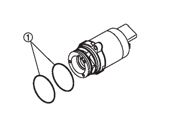
5. Install O-rings  to actuator assembly.
 to actuator assembly.
| caution |
|
6. Set electro-hydraulic coupling assembly in a vertical position before Installing actuator assembly.
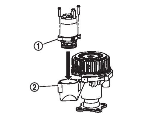
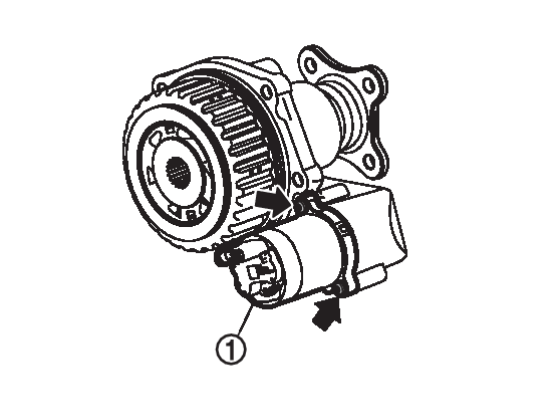
7. Install actuator assembly  to electro-hydraulic coupling assembly
  and tighten mounting bolts evenly to the specified torque.
 to electro-hydraulic coupling assembly
  and tighten mounting bolts evenly to the specified torque.
- For tightening torque, refer to Exploded View
 .
.
| caution |
|
8. Measure and search for the maximum point of drive pinion runout. Refer to Adjustment .
.
 .
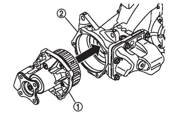
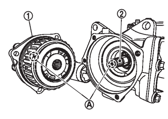
.9. Match electro-hydraulic coupling assembly  to spline of drive pinion, then install it to final drive assembly
  .
.
 to spline of drive pinion, then install it to final drive assembly
  .
.| caution | Aligning marking  on drum of electro-hydraulic coupling assembly on drum of electro-hydraulic coupling assembly  and marking and marking  on tip of drive pinion on tip of drive pinion  . . |
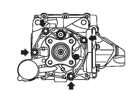
10. Tighten electro-hydraulic coupling assembly mounting bolts to the specified torque diagonally.
- For tightening torque, refer to Exploded View
 .
.
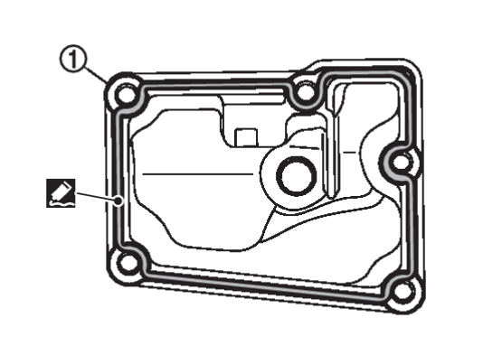
11. Apply liquid gasket to mating surface of coupling oil tank cover  .
.
 .
.- For applying liquid gasket, refer to Exploded View
 .
.
| caution |
|
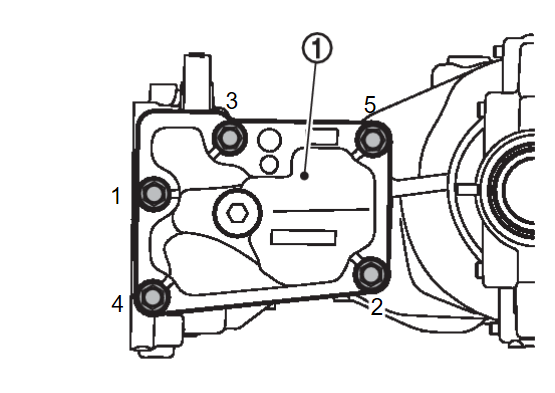
12. Install coupling oil tank cover  to gear carrier and tighten the mounting bolts to the specified torque in the order shown in the figure.
 to gear carrier and tighten the mounting bolts to the specified torque in the order shown in the figure.
- For tightening torque, refer to Exploded View
 .
.
13. Check companion flange runout. Refer to Adjustment .
.
 .
.14. Fill with electro-hydraulic coupling oil after installing final drive assembly to the vehicle. Refer to Adjustment .
.
 .
.![[Previous]](../../../buttons/fprev.png)
![[Next]](../../../buttons/fnext.png)
 from gear carrier
  , if necessary.