Adjustment
DRIVE PINION RUNOUT
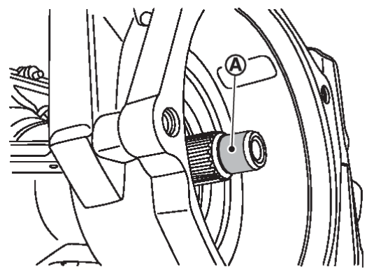
1. Set pinion nut wrench [SST: KV38109900 (J-53029)] on drive pinion lock nut.
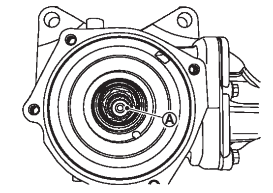
3. Rotate the drive pinion with pinion nut wrench [SST: KV38109900 (J-53029)] to measure drive pinion runout.
| Drive pinion runout | : Refer to Drive Pinion Runout . . |
- If the runout is outside of the repair limit, check drive pinion assembly condition; drive pinion may be deformed etc.
caution Replace drive gear and drive pinion as a set.
COMPANION FLANGE RUNOUT
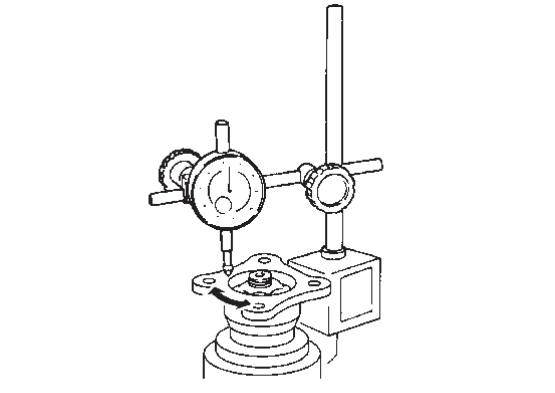
1. Fit a dial indicator onto the companion flange face (inner side of the propeller shaft mounting bolt holes).
2. Rotate companion flange to check for runout.
| Companion flange face runout | : Refer to Companion Flange Runout . . |
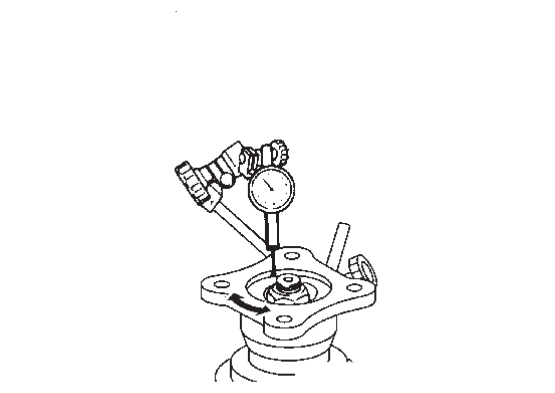
4. Rotate companion flange to check for runout.
| Inner side of the companion flange runout | : Refer to Companion Flange Runout . . |
5. If the runout value is outside the runout limit, follow the procedure below to adjust.
(1) Check for runout while changing the phase between companion flange and shaft of electro-hydraulic coupling by 90° step, and search for the position where the runout is the minimum.
(2) If the runout value is still outside of the limit after the phase has been changed, replace companion flange.
(3) Adjust assembly status of electro-hydraulic coupling, or replace electro-hydraulic coupling assembly if runout is outside the limit after the companion flange is replaced.
![[Previous]](../../../buttons/fprev.png)
![[Next]](../../../buttons/fnext.png)
 part of drive pinion tip.


