DTC 22: Stoplight Switch System.
CIRCUIT OPERATION
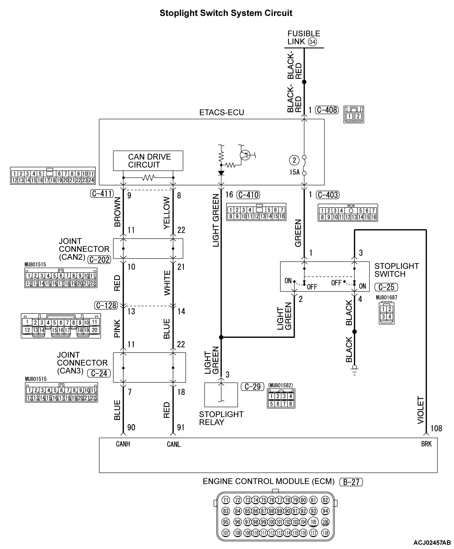
- For the stoplight switch, two switches, a stoplight switch for the stoplight illumination and a brake switch exclusively for the cruise control system, are incorporated to improve the reliability.
- As for the stoplight switch, when the brake pedal is depressed/released, the stoplight switch ON/OFF signal is transmitted from the ETACS-ECU to the ECM via CAN bus line.
- As for the brake switch, the ECM connector B-27 terminal number 108 monitor the state of the brake switch. The brake switch turn ON/OFF when the brake pedal is depressed/released, and the input signal to the ECM connector B-27 terminal number 108 changes. According to this change, the ECM judges the state of the brake switch.
DTC SET CONDITIONS
Check Condition
- The "CRUISE" indicator light illuminates.
Judgment Criteria
- Open/short in stoplight switch circuit.
- Open circuit in the brake switch circuit (between ECM connector B-27 terminal number 108 and body ground.)
- Malfunction of CAN bus line.
TROUBLESHOOTING HINTS (THE MOST LIKELY CAUSES FOR THIS CASE:)
- Malfunction of CAN bus system.
- Damaged harness or connector.
- Malfunction of the fuse No.2 at the ETACS-ECU.
- Malfunction of the stoplight switch.
- Malfunction of the stoplight relay.
- Malfunction of the ETACS-ECU.
- Malfunction of the ECM.
DIAGNOSIS
| caution | If there is any problem in the CAN bus lines, an incorrect DTC may be set. Prior to this diagnosis, diagnose the CAN bus lines (Refer to GROUP 54C, Trouble code diagnosis  .) .) |
STEP 1. Using scan tool MB991958, diagnose the CAN bus line.
(1)
| caution | To prevent damage to scan tool MB991958, always turn the ignition switch to the "LOCK" (OFF) position before connecting or disconnecting scan tool MB991958. |
(2) Turn the ignition switch to the "ON" position.
Is the check result satisfactory?
STEP 2. Using scan tool MB991958, check the data list item 74: Brake light switch.
(2) Turn the ignition switch to the "ON" position.
(3) Set scan tool MB991958 to data reading mode for cruise control system (Refer to  ).
).
 ).
).- Item 74: Brake light switch.
- When the brake pedal is depressed, the display on scan tool MB991958 should be "ON".
- When the brake pedal is released, the display on scan tool MB991958 should be "OFF".
Is the switch operating properly?
STEP 3. Check the stoplight operation.
Check the stoplight operation.
OK:
- Brake pedal depressed: Stoplight will illuminate
- Brake pedal not depressed: Stoplight does not illuminate
Is the stoplight operating properly?
STEP 4. Using scan tool MB991958, check the ETACS system data list item 290: Brake light switch.
(2) Turn the ignition switch to the "ON" position.
(3) Set scan tool MB991958 to data reading mode for ETACS system (Refer to GROUP 54A, Data List Reference Table  ).
).
 ).
).- Item 290: Brake light switch.
- When the brake pedal is depressed, the display on scan tool MB991958 should be "ON".
- When the brake pedal is released, the display on scan tool MB991958 should be "OFF".
Is the switch operating properly?
STEP 5. Using scan tool MB991958, check the data list item 74: Brake light switch.
(2) Turn the ignition switch to the "ON" position.
(3) Set scan tool MB991958 to data reading mode for cruise control system (Refer to  ).
).
 ).
).- Item 74: Brake light switch.
- When the brake pedal is depressed, the display on scan tool MB991958 should be "ON".
- When the brake pedal is released, the display on scan tool MB991958 should be "OFF".
Is the switch operating properly?
STEP 6. Using scan tool MB991958, check the data list item 89: Normally closed brake switch.
(2) Turn the ignition switch to the "ON" position.
(3) Set scan tool MB991958 to data reading mode for cruise control system (Refer to  ).
).
 ).
).- Item 89: Normally closed brake switch.
- When the brake pedal is depressed, the display on scan tool MB991958 should be "ON".
- When the brake pedal is released, the display on scan tool MB991958 should be "OFF".
Is the switch operating properly?
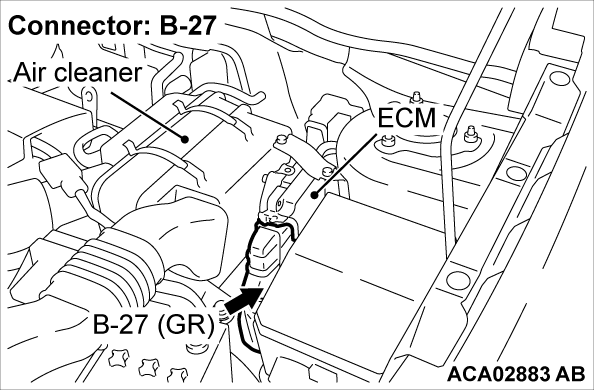
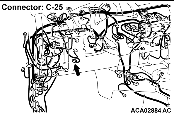
STEP 7. Check ECM connector B-27 and stoplight switch connector C-25 for loose, corroded or damaged terminals, or terminals pushed back in the connector.
Refer to GROUP 00E, Harness Connector Inspection  .
.
 .
.Are the connectors and terminals in good condition?
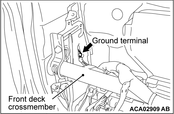
STEP 8. Check the harness wire between ECM connector B-27 terminal number 108 and stoplight switch connector C-25 terminal number 3, and between stoplight switch connector C-25 terminal number 4 and body ground, for damage.
Check harness wire for open/short circuit and damage.
Are the harness wires in good condition?
STEP 9. Check the stoplight switch.
Refer to GROUP 35A, Brake Pedal, Inspection - Stoplight Switch Check  .
.
 .
.Is the stoplight switch operating properly?
STEP 10. Using scan tool MB991958, check the data list item 89: Normally closed brake switch.
(2) Turn the ignition switch to the "ON" position.
(3) Set scan tool MB991958 to data reading mode for cruise control system (Refer to  ).
).
 ).
).- Item 89: Normally closed brake switch.
- When the brake pedal is depressed, the display on scan tool MB991958 should be "ON".
- When the brake pedal is released, the display on scan tool MB991958 should be "OFF".
Is the switch operating properly?
STEP 11. Read the cruise control system DTC.
(1) Disconnect the negative (-) battery terminal, to erase the DTC of the cruise control system.
(2) Connect the negative (-) battery terminal.
(3) Turn the ignition switch to the "ON" position, and press the "CRUISE ON/OFF" switch to turn the cruise control system to ON (turn on the "CRUISE" indicator light.)
(4) With the cruise control switches not operated, depress the brake pedal for several seconds, and then read the DTC of the cruise control system (Refer to  .)
.)
 .)
.)Is DTC 22 set?
STEP 12. Using scan tool MB991958, check the data list item 74: Brake light switch, item 89: Normally closed brake switch.
(2) Turn the ignition switch to the "ON" position.
(3) Set scan tool MB991958 to data reading mode for cruise control system (Refer to  .)
.)
 .)
.)- Item 74: Brake light switch.
- When the brake pedal is depressed, the display on scan tool MB991958 should be "ON."
- When the brake pedal is released, the display on scan tool MB991958 should be "OFF."
- Item 89: Normally closed brake switch.
- When the brake pedal is depressed, the display on scan tool MB991958 should be "ON."
- When the brake pedal is released, the display on scan tool MB991958 should be "OFF."
Is the switch operating properly?
STEP 13. Read the cruise control system DTC.
(1) Disconnect the negative (-) battery terminal, to erase the DTC of the cruise control system.
(2) Connect the negative (-) battery terminal.
(3) Turn the ignition switch to the "ON" position, and press the "CRUISE ON/OFF" switch to turn the cruise control system to ON (turn on the "CRUISE" indicator light.)
(4) With the cruise control switches not operated, depress the brake pedal for several seconds, and then read the DTC of the cruise control system (Refer to  .)
.)
 .)
.)Is DTC 22 set?
 The procedure is complete.
![[Previous]](../../../buttons/fprev.png)
![[Next]](../../../buttons/fnext.png)


