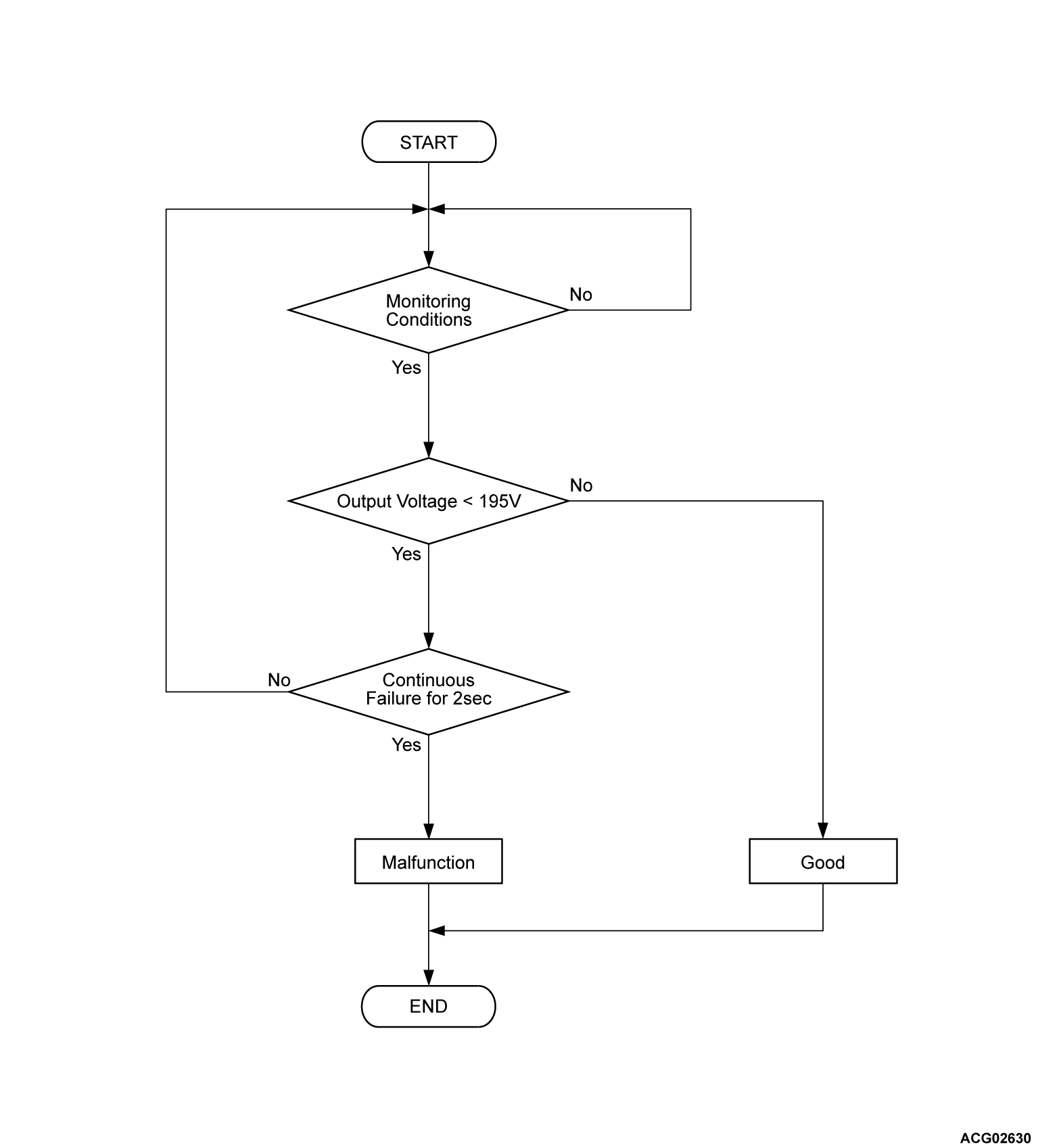
DTC P1D08: Load Connection Abnormal
MONITOR EXECUTION
- Continuous
MONITOR EXECUTION CONDITIONS (Other monitor and Sensor)
Other Monitor (There is no temporary DTC set in memory for the item monitored below)
- Battery charger control module (OBC) monitor
- EV CAN monitor
Sensor (The sensor below is determined to be normal)
- Not applicable
DTC SET CONDITIONS
Check Conditions
- The EV system or the charging system is activated or the charge permission from PHEV-ECU is on.
Judgment Criterion
- Change of the output voltage is more than 195 volts for 2 seconds.
FAIL-SAFE AND BACKUP FUNCTION
- The charge is stopped.
PROBABLE CAUSES
- Open circuit or harness damage in high voltage circuits between on board charger/DC-DC converter and drive battery, or loose connector contact.
- The high voltage fuse is melted down inside the REMCU.
- The on board charger/DC-DC converter is failed
DIAGNOSIS
Required Special Tools
- MB991223: Wiring harness set
- MB992006: Extra fine probe
| danger | When high voltage system components are served, be sure to pull service plugs to shut down high voltage (Refer to  ). ). |
| danger | When pulling service plugs, wear the specified protective equipment (Refer to  ). ). |
STEP 1. Using scan tool (M.U.T.-IIISE), check whether the other system DTC is set.
STEP 2. Perform the continuity check of the high voltage fuse inside the REMCU.
Check of the high-voltage fuse inside inverter (Refer to GROUP 54Db - Check and Replacement of the High-voltage Fuse inside the Inverter  ).
).
 ).
).Is the check result normal?
STEP 3. Check of open circuit and damage in P line and N line between on board charger/DC-DC converter connector and drive battery connector.
Is the check result normal?
STEP 4. Test the OBD-II drive cycle.
(2) Check the DTC.
Is the DTC set?
![[Previous]](../../../buttons/fprev.png)
![[Next]](../../../buttons/fnext.png)


