DTC P1D61: BATT.CHGR Temperature Sensor Characteristic Abnormal
DTC P1D64: BATT.CHGR PFC Temperature sensor Short to Ground
DTC P1D65: BATT.CHGR PFC Temperature sensor Short to Power Supply
DTC P1D66: BATT. CHGR Inverter Temperature Sensor Short to Ground
DTC P1D67: BATT. CHGR Inverter Temperature Sensor Short to Power Supply
DTC P1D68: BATT. CHGR Inverter Temperature Sensor Short to Ground 2
DTC P1D69: BATT. CHGR Inverter Temperature Sensor Short to Power Supply 2
DESCRIPTIONS OF MONITOR METHODS <DTC P1D61>
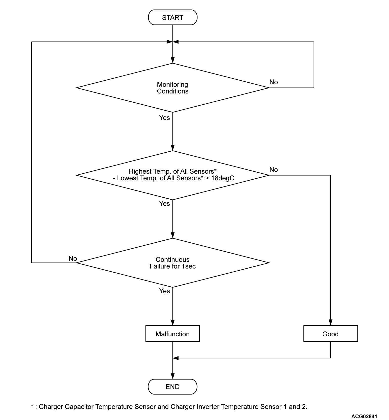
3 temperature sensors (charger capacitor temperature sensor, charger inverter temperature sensor 1, charger inverter temperature sensor 2) are monitored by comparing the maximum and minimum temperature of these sensors.
MONITOR EXECUTION
- Continuous
MONITOR EXECUTION CONDITIONS (Other monitor and Sensor)
Other Monitor (There is no temporary DTC set in memory for the item monitored below)
- Battery charger control module (OBC) monitor
Sensor (The sensor below is determined to be normal)
- Not applicable
DTC SET CONDITIONS
Check Conditions <DTC P1D61>
- OBC power supply voltage is 10 volts to 16 volts.
- Charge permission from PHEV-ECU is off.
- Time after above condition satisfied is more than 240 seconds.
Judgment Criterion <DTC P1D61>
- When the difference between the value of the highest temperature of all sensors and the value of the lowest temperature of all sensors remains at 64°F (18°C) or less for 1 second
note All sensor: Charger capacitor temperature sensor, charger inverter temperature sensor 1 and charger inverter temperature sensor 2
Check Conditions <DTC P1D64, P1D65, P1D66, P1D67, P1D68, P1D69>
- OBC power supply voltage is 10 volts to 16 volts.
Judgment Criterion <DTC P1D64, P1D66, P1D68>
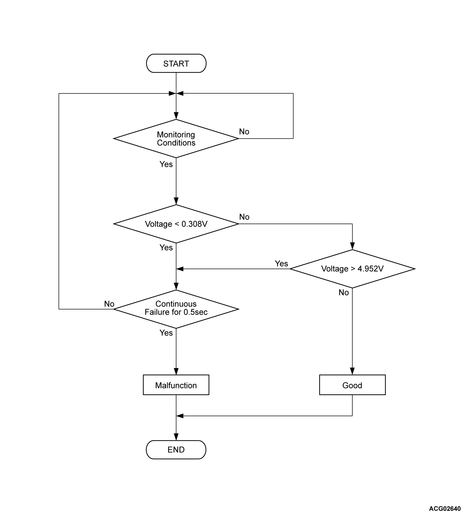
- Change of the charger temperature sensor voltage is less than 0.308 volt [more than 302°F (150°C)] for 0.5 second.
Judgment Criterion <DTC P1D65, P1D67, P1D69>
- Change of the charger temperature sensor voltage is more than 4.952 volts [less than -61°F (-52°C)] for 0.5 second.
OBD-II DRIVE CYCLE PATTERN <DTC P1D61>
FAIL-SAFE AND BACKUP FUNCTION
- The charge is stopped.
PROBABLE CAUSES
- The cooling system is failed.
- The on board charger/DC-DC converter is failed.
DIAGNOSIS
STEP 1. Using scan tool (M.U.T.-IIISE), check on board charger/DC-DC converter data list.
Are the check result normal?
STEP 2. Check the cooling system.
Is the check result normal?
![[Previous]](../../../buttons/fprev.png)
![[Next]](../../../buttons/fnext.png)


