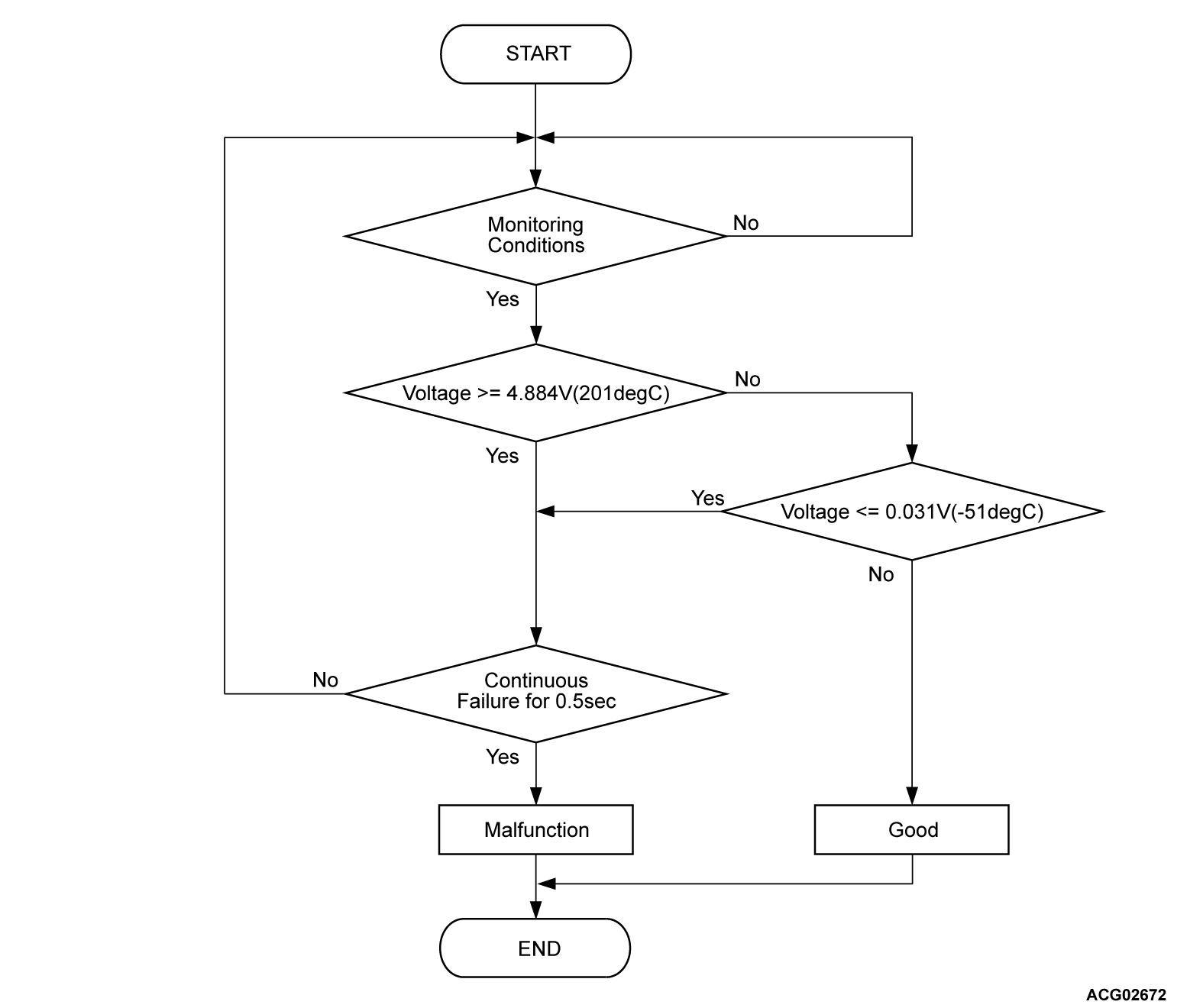
DTC P1059: Generator control unit oil temperature sensor fails (short to power supply, short circuit)
DTC P105A: Generator control unit oil temperature sensor fails (short to ground, open circuit)
DTC P105A: Generator control unit oil temperature sensor fails (short to ground, open circuit)
MONITOR EXECUTION
- Continuous
MONITOR EXECUTION CONDITIONS (Other monitor and Sensor)
Other Monitor (There is no temporary DTC stored in memory for the item monitored below)
- Not applicable
Sensor (The sensor below is determined to be normal)
- Not applicable
DTC SET CONDITIONS
Check Conditions
- Power drive unit (GCU) power supply voltage is 8 volts to 16 volts.
Judgment Criterion <DTC P1059>
- Change of the power drive unit (GCU) IGBT temperature sensor voltage is more than 4.884 volts [201°C (394°F)] for 0.5 second.
Judgment Criterion <DTC P105A>
- Change of the power drive unit (GCU) voltage is less than 0.031 volt [-51°C (-60°F)] for 0.5 second.
PROBABLE CAUSES
- The thermistor oil temperature circuit fails
- Malfunction of the generator
- Malfunction of the power drive unit [generator control unit (GCU)]
- Damaged wiring harness
DIAGNOSIS
Required Special Tools
- MB991223: Wiring harness set
- MB992006: Extra fine probe
STEP 1. Using scan tool (M.U.T.-IIISE), check whether the DTC is set.
Check if the DTC P104C is set in the power drive unit [generator control unit (GCU)].
Is the DTC set?
STEP 2. Check the resistance in the oil temperature sensor.
(1) Disconnect the power drive unit connector.
(2) Check the conduction of the harness between the power drive unit and the generator and measure the resistance value of the oil temperature sensor in the power drive unit connector terminals.
|
Is the check result normal?
![[Previous]](../../../buttons/fprev.png)
![[Next]](../../../buttons/fnext.png)


