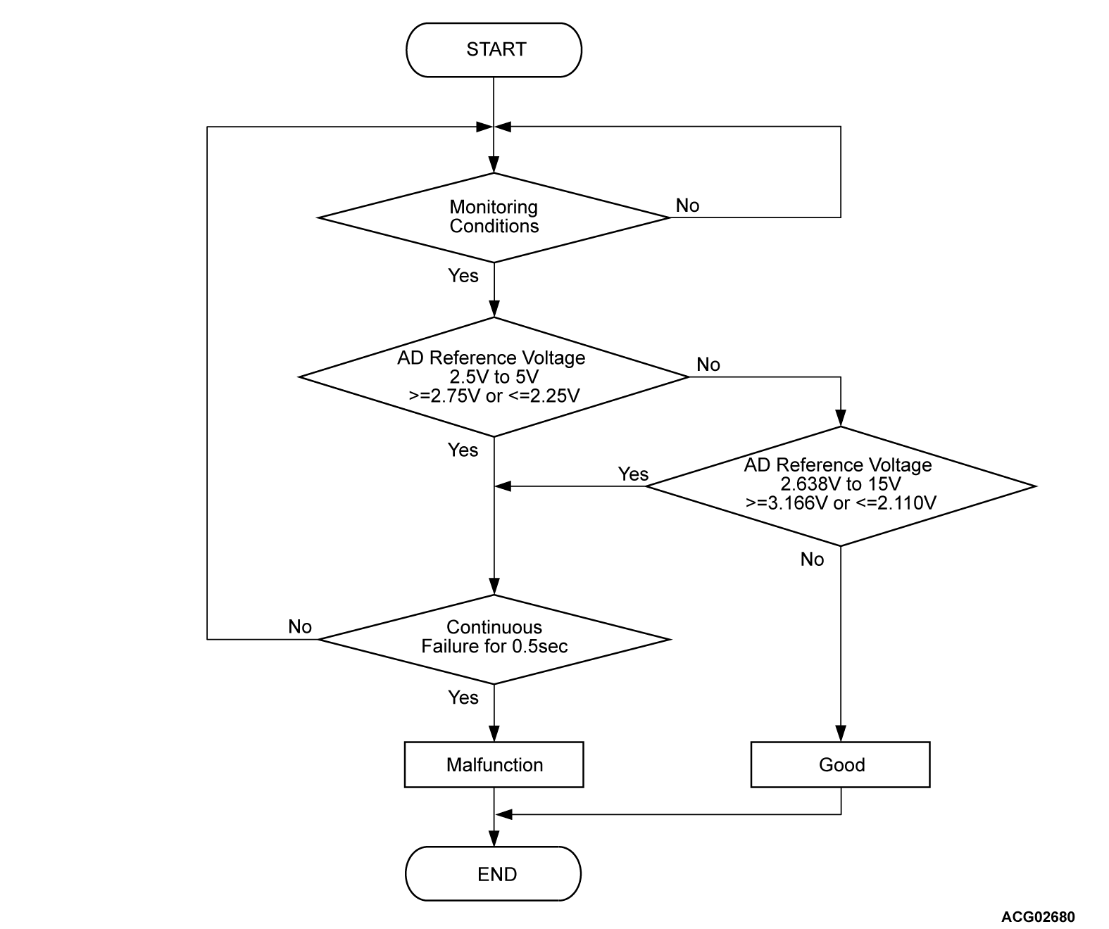
DTC P104C: AD module fails
MONITOR EXECUTION
- Continuous
MONITOR EXECUTION CONDITIONS (Other monitor and Sensor)
Other Monitor (There is no temporary DTC stored in memory for the item monitored below)
- Not applicable
Sensor (The sensor below is determined to be normal)
- Not applicable
DTC SET CONDITIONS
Check Conditions
- Power drive unit (GCU) power supply voltage is 8 volts to 16 volts.
Judgment Criterion
- AD reference voltage 2.5V to 5V is no more than 2.25 volt or not less than 2.75 volt
- AD reference voltage 2.638V to 15V is no more than 2.11 volt or not less than 3.166 volt
PROBABLE CAUSES
Malfunction of the power drive unit [generator control unit (GCU)]
![[Previous]](../../../buttons/fprev.png)
![[Next]](../../../buttons/fnext.png)


