BRAKE PEDAL INSPECTION
| caution | Do not apply grease or lubricant to the switch and the switch installation section to avoid malfunction of the switch. In addition, do not use gloves which have grease on them. |
BRAKE PEDAL HEIGHT CHECK
1. Turn up the floor carpet under the brake pedal.
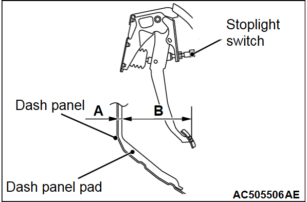
3. Use a needle or similar tool to measure the dimension A in the figure (distance from the dash panel pad surface to the dash panel).
4. Measure the dimension B in the figure (distance from the pedal pad surface to the dash panel pad surface).
5. Make sure that the total of the dimensions A and B measured in Steps 2 and 3 (brake pedal height) is within the standard value.
Standard value (A + B): 221.8 - 227.8 mm (8.7 - 9.0 inch)
6. When the brake pedal height is not within the standard value, inspect the brake pedal in the following procedure.
(2) Check the removed brake pedal assembly for distortion, and replace it when deformed (Refer to  ).
).
 ).
).(4) Measure the brake pedal height again, and make sure that it is within the standard value (A + B).
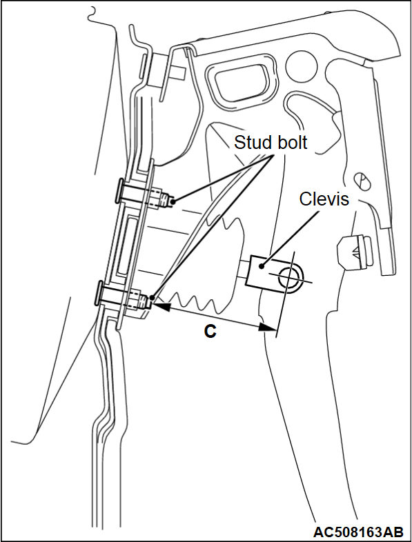
When the measured value is not within the standard value, measure the dimension C in the figure (distance from the stud bolt end to the clevis hole center), and make sure it is within the standard value (C).
When the measured value is not within the standard value, measure the dimension C in the figure (distance from the stud bolt end to the clevis hole center), and make sure it is within the standard value (C).
Standard value (C): 75.8 - 80.2 mm (2.98 - 3.16 inch)
7. After checking the brake pedal height, install the stoplight switch in the following procedure:
(1) Insert the stoplight switch into the key hole on the plate.
(2) While holding the brake pedal upwards, push in the stoplight switch to the stop position.
(3) Lock the stoplight switch body by twisting it clockwise.
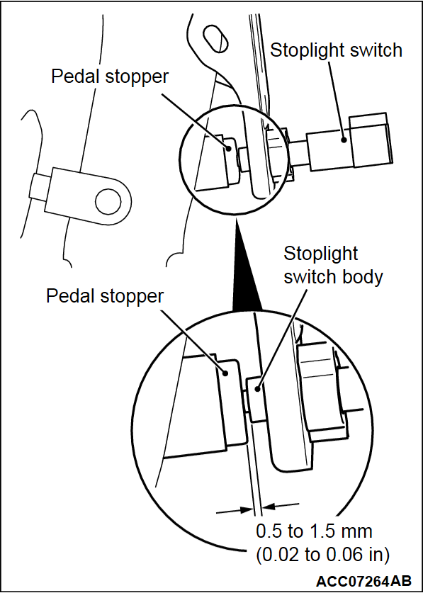
(4) Check that the clearance between the stoplight switch and the pedal stopper is as shown in the figure.
(5)
| caution | Make sure that the stoplight is not illuminated when the brake pedal is not depressed. |
Connect the stoplight switch connector.
8. Check the key interlock mechanism and the shift lock mechanism (Refer to GROUP 23A - On-vehicle Service, Shift Lock Mechanism Check  <CVT> or GROUP 23C - On-vehicle Service, Shift Lock Mechanism Check
  <A/T>).
 <CVT> or GROUP 23C - On-vehicle Service, Shift Lock Mechanism Check
  <A/T>).
9. Recover the floor carpet under the brake pedal.
BRAKE PEDAL PLAY CHECK AND ADJUSTMENT
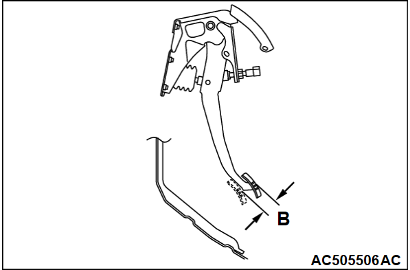
1. With the engine stopped, depress the brake pedal 2 or 3 times to relieve the vacuum in the brake booster. Then, press the brake pedal with your finger and check if the pedal stroke until the pedal becomes heavy (play) is within the standard value.
Standard value (B): 3 - 8 mm (0.12 - 0.31 inch)
2. When the brake pedal play is not within the standard value, check the brake pedal-to-clevis pin looseness, clevis pin-to-booster operating rod looseness, brake pedal height, and stoplight switch position, and adjust or replace as necessary.
BRAKE PEDAL-TO-FLOOR PANEL CLEARANCE CHECK AND ADJUSTMENT
1. Turn up the floor carpet under the brake pedal.
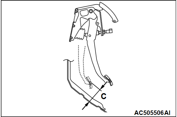
2. Start the engine and depress the brake pedal with approximately 500 N (112 pounds), and measure clearance between the brake pedal and the floor panel.
Standard value (C): 65 mm (2.6 inch) or more
3. When the clearance is not within the standard value, check for the air in the brake line and thickness of the disc brake pad, and correct or replace as necessary.
4. Recover the floor carpet under the brake pedal.
![[Previous]](../../../buttons/fprev.png)
![[Next]](../../../buttons/fnext.png)
