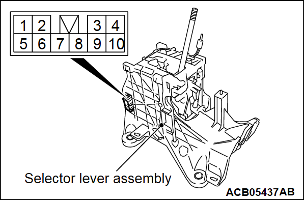
SHIFT LOCK MECHANISM CHECK
SYSTEM CHECK
| Inspection procedure | Check conditions | Items to be checked (Normal conditions) | Possible cause of abnormality | |
| 1 | Brake pedal not depressed | Ignition switch position: Other than "ON" | The selector lever cannot be moved out of the "P" position |
|
| 2 | Brake pedal depressed |
| ||
| 3 | Brake pedal not depressed | Ignition switch position: "ON" |
| |
| 4 | Brake pedal depressed | The selector lever can be moved from the "P" position to other positions smoothly. |
| |
| 5 | Shift lock release button pressed |
| ||
| 6 | Brake pedal depressed / not depressed | The selector lever can be moved from the "R" position to the "P" position smoothly. |
| |
COMPONENT PARTS CHECK
SHIFT LOCK LINK
Check each part for damage and disengagement.
![[Previous]](../../../buttons/fprev.png)
![[Next]](../../../buttons/fnext.png)
